 |
b5r5za00000446
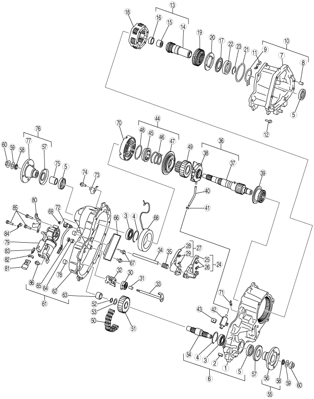
TRANSFER CASE DISASSEMBLY
id031600501100
Exploded View
b5r5za00000446
|
|
1
|
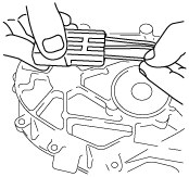
Center transfer case
|
|
2
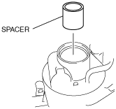
|
Dowel pin
|
|
3
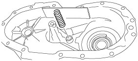
|
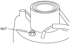
Bearing
|
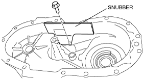
|
4
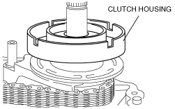
|
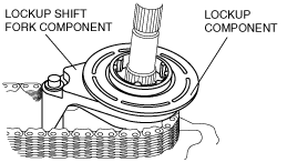
Snap ring
|
|
5
|
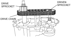
Oil seal
|
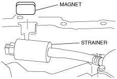
|
6
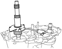
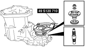
|
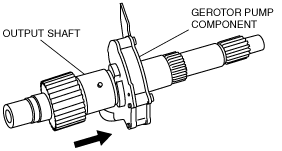
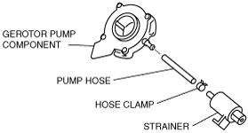
Center transfer case component
|
|
7
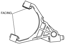
|
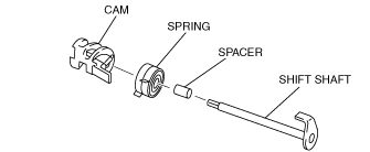
Front transfer case
|
|
8
|
Dowel pin
|
|
9
|
Snap ring
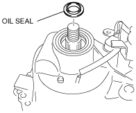
|
|
10
|
Front transfer case component
|
|
11
|
Clip
|
|
12
|
Bolt
|
|
13
|
Input shaft component
|
|
14
|
Input shaft
|
|
15
|
Needle bearing
|
|
16
|
Bushing
|
|
17
|
Thrust washer
|
|
18
|
Planetary gear component
|
|
19
|
Sun gear
|
|
20
|
Thrust plate
|
|
21
|
Snap ring
|
|
22
|
Ball bearing
|
|
23
|
Snap ring
|
|
24
|
Reduction shift fork component
|
|
25
|
Reduction shift fork
|
|
26
|
Reduction shift fork facing
|
|
27
|
Lockup shift fork component
|
|
28
|
Lockup shift fork
|
|
29
|
Lockup shift fork facing
|
|
30
|
Spring
|
|
31
|
Spacer
|
|
32
|
Cam
|
|
33
|
Shift shaft
|
|
34
|
Rail shift
|
|
35
|
Return spring
|
|
36
|
Output shaft and gerotor pump component
|
|
37
|
Output shaft component
|
|
38
|
Gerotor pump component
|
|
39
|
Reduction hub
|
|
40
|
Pump hose
|
|
41
|
Hose clamp
|
|
42
|
Oil strainer
|
|
43
|
Magnet
|
|
44
|
Lockup component
|
|
45
|
Lockup hub
|
|
46
|
Spring
|
|
47
|
Lockup collar
|
|
48
|
Snap ring
|
|
49
|
Drive sprocket
|
|
50
|
Drive chain
|
|
51
|
Driven sprocket
|
|
52
|
Snap ring
|
|
53
|
Spacer
|
|
54
|
Lower output shaft
|
|
55
|
Front output flange component
|
|
56
|
Front output flange
|
|
57
|
Deflector
|
|
58
|
Oil seal
|
|
59
|
Washer
|
|
60
|
Locknut
|
|
61
|
Rear transfer case component
|
|
62
|
Rear transfer case
|
|
63
|
Needle bearing
|
|
64
|
Sleeve
|
|
65
|
Seal
|
|
66
|
Snubber
|
|
67
|
Bolt
|
|
68
|
Clutch coil
|
|
69
|
Nut
|
|
70
|
Clutch housing
|
|
71
|
Breather pipe
|
|
72
|
Speed sensor component
|
|
73
|
Bracket
|
|
74
|
Bolt
|
|
75
|
Spacer
|
|
76
|
Rear companion flange component
|
|
77
|
Rear companion flange
|
|
78
|
Oil plug
|
|
79
|
Motor component
|
|
80
|
Bracket
|
|
81
|
Terminal connector
|
|
82
|
Clip
|
|
83
|
Bracket
|
|
84
|
Clip
|
|
85
|
Bolt
|
|
86
|
Bolt
|
Disassembly Procedure
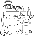
1. Position the transfer case on repair fixture as shown in the picture.
b5r5za00000299
|
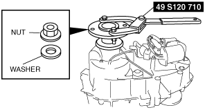
2. Secure the rear companion flange component using the SST.
b5r5za00000480
|
3. Remove the nut and washer.
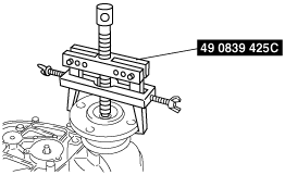
4. Remove the rear companion flange using the SST.
b5r5za00000481
|
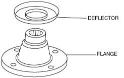
5. Remove the deflector from the flange.
b5r5za00000469
|
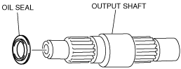
6. Remove the oil seal from the output shaft.
b5r5za00000456
|
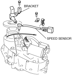
7. Remove the bracket and speed sensor.
arnffv00000614
|
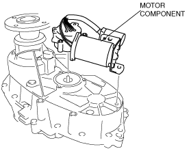
8. Remove the motor component.
arnffv00000619
|
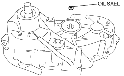
9. Remove the oil seal.
b5r5za00000508
|
10. Remove the clutch coil terminal from the connector and pull out the wiring harness from the sleeve.
b5r5za00000304
|
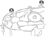
11. Remove the two oil plugs from the rear transfer case.
b5r5za00000305
|
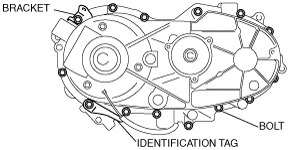
12. Remove the 14 bolts and the identification tag.
b5r5za00000429
|
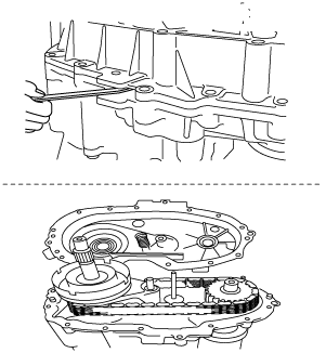
13. Pry at the transfer case projection as shown in the figure using a flathead screwdriver, and remove the rear transfer case from the center transfer case.
b5r5za00000411
|
14. Remove the spacer.
b5r5za00000457
|
15. Using a flathead screwdriver, remove the oil seal.
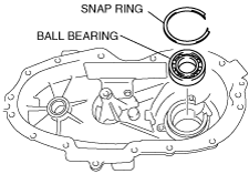
16. Remove the snap ring.
b5r5za00000430
|
17. Using the SST, pull out the ball bearing from the rear transfer case.
b5r5za00000482
|
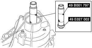
18. Using the SST, pull out the needle bearing from the rear transfer case.
b5r5za00000483
|
19. Remove the return spring.
b5r5za00000309
|
20. Remove the 3 nuts.
b5r5za00000310
|
21. Remove the clutch coil from the rear transfer case.
22. Remove the snubber from the rear transfer case.
b5r5za00000412
|
23. Clean and remove the sealant of the rear transfer case and center transfer case.
24. Remove the clutch housing from the output shaft.
b5r5za00000312
|
25. Slide the lockup component and the lockup shift fork component as a single unit to remove the lockup component from the output shaft.
b5r5za00000448
|
26. Remove the lockup shift fork component from the lockup component.
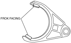
27. Remove the two fork facings from the lockup shift fork.
b5r5za00000459
|
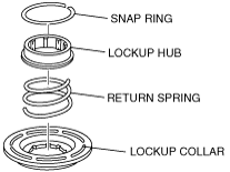
28. Remove the snap ring, lockup hub and return spring from the lockup collar.
b5r5za00000449
|
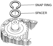
29. Remove the snap ring and spacer from the output shaft.
b5r5za00000450
|
30. Remove the drive chain, driven sprocket and drive sprocket from the output shaft at a time.
b5r5za00000406
|
31. Separate the drive chain and sprockets.
32. Remove the magnet from the slot in the center transfer case.
b5r5za00000451
|
33. Remove the strainer from the center transfer case.
34. Remove the output shaft component and gerotor pump component.
b5r5za00000453
|
35. Remove the gerotor pump component from the output shaft.
b5r5za00000408
|
36. Loosen the hose clamp and remove the pump hose from the gerotor pump component.
37. Remove the hose clamp, pump hose and strainer.
b5r5za00000460
|
38. Remove the reduction hub, reduction shift fork component, rail shaft and shift shaft component from the center transfer case.
b5r5za00000320
|
39. Remove the two shift fork facings from the reduction shift fork component.
b5r5za00000432
|
40. Disassemble the cam, spring, spacer, and shift shaft.
b5r5za00000458
|
41. Secure the flange using the SST.
b5r5za00000484
|
42. Remove the nut and washer.
43. Remove the deflector from the flange.
b5r5za00000469
|
44. Pull out the front output flange component.
45. Remove the lower output shaft.
46. Remove the oil seal from the lower output shaft.
b5r5za00000467
|
47. Remove the deflector from the flange only when replacement is necessary.
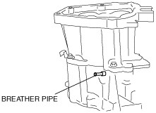
48. Remove the breather pipe.
b5r5za00000421
|
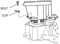
49. Remove the front transfer case six bolts.
arnffv00000620
|
50. Remove the front transfer case by separating the adapter sealer bond using a flathead screwdriver.
51. Remove the input shaft component and planetary gear component from the front transfer case.
b5r5za00000479
|
52. Remove the snap ring from the front transfer case.
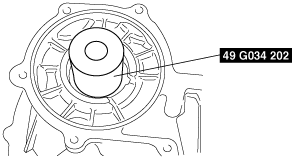
53. Using the SST, remove the oil seal from the front transfer case.
b5r5za00000487
|
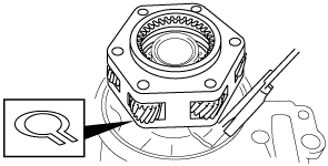
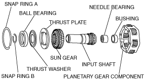
54. Remove the snap ring A.
b5r5za00000324
|
55. Pull out the input shaft component and sun gear from the planetary gear component.
56. Remove the snap ring B.
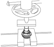
57. Remove the ball bearing, thrust washer, thrust plate and from the input shaft using the press.
arnffv00000603
|
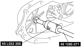
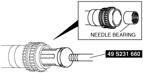
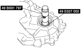
58. Using the SST, remove the needle bearing from the input shaft component.
b5r5za00000507
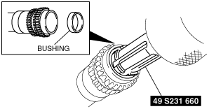
|
59. Using the SST, remove the bushing from the input shaft component.
b5r5za00000506
|
60. Using a flathead screwdriver, remove the oil seal.
b5r5za00000416
|
61. Remove the snap ring.
62. Using the SST, remove the ball bearing.
b5r5za00000486
|
63. Remove the dowel pins from the center transfer case.
b5r5za00000326
|