 |
b5r5za00000130
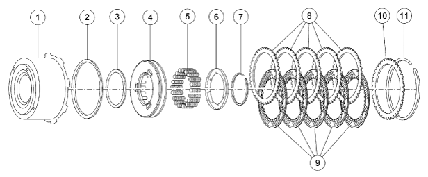
INTERMEDIATE BRAKE AND DIRECT CLUTCH DRUM COMPONENT DISASSEMBLY/ASSEMBLY
id051300262200
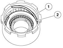
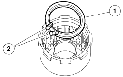
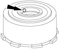
Intermediate Brake and Direct Clutch Drum Component
b5r5za00000130
|
|
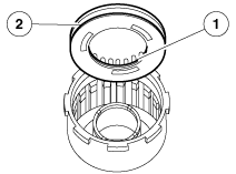
1
|
Intermediate brake drum
|
|
2
|
Direct clutch piston outer seal ring
|
|
3
|
Direct clutch piston inner seal ring
|
|
4
|
Direct clutch piston
|
|
5
|
Direct clutch piston spring (20 required)
|
|
6
|
Direct clutch piston spring retainer
|
|
7
|
Retaining ring
|
|
8
|
Direct clutch external spline plate (steel)
|
|
9
|
Direct clutch internal spline plates (friction)
|
|
10
|
Direct clutch pressure plate
|
|
11
|
Retaining ring (select fit)
|
Disassembly
1. Remove the retaining ring and the direct clutch pressure plate.
b5r5za00000131
|
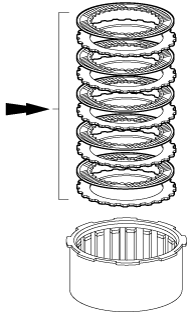
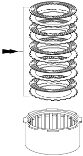
2. Remove the direct clutch disc pack.
b5r5za00000132
|
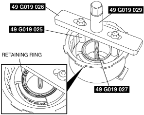
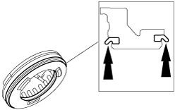
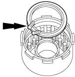
3. Using the SST, remove the retaining ring.
b5r5za00000377
|
4. Relieve the direct clutch spring tension and remove the SST.
5. Remove the direct clutch piston spring retainer and the direct clutch piston springs.
b5r5za00000134
|
6. Using compressed air, remove the direct clutch piston from the intermediate brake drum.
b5r5za00000135
|
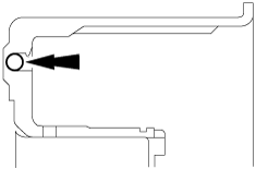
7. Remove and discard the direct clutch piston inner and outer seal.
b5r5za00000136
|
Assembly
1. Install the new direct clutch piston inner seal ring and the direct clutch piston outer seal ring.
b5r5za00000137
|
2. Inspect the clutch components for damage or wear. Install new components as necessary.
b5r5za00000139
|
3. Install the direct clutch piston.
b5r5za00000378
|
4. Install the direct clutch piston springs and the retainer.
b5r5za00000141
|
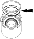
5. Using the SST, install the retaining ring.
b5r5za00000377
|
6. Relieve the direct clutch spring tension and remove the SST.
7. When installing friction plates, the word TOP should face up. If reusing plates, grooves must be installed clockwise. Install the direct clutch disc pack.
b5r5za00000142
|
8. Install the steel clutch plates and friction clutch plates in alternating order starting with a steel clutch plate.
b5r5za00000143
|
9. Install the direct clutch pressure plate using the original retaining ring.
b5r5za00000144
|
10. Air check the assembly.
b5r5za00000135
|
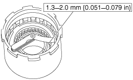
11. Push down on the direct clutch disc pack and check the gap between the direct clutch retaining ring and the direct clutch pressure plate with a feeler gauge.
b5r5za00000145
|
Retaining ring size for direct clutch clearance
|
Thickness |
Diameter |
||
|---|---|---|---|
|
mm |
in |
mm |
in |
|
1.37
|
0.0539
|
130.1
|
5.122
|
|
1.73
|
0.0681
|
130.1
|
5.122
|
|
2.08
|
0.0819
|
130.1
|
5.122
|
|
2.44
|
0.0961
|
130.1
|
5.122
|