 |
absggn00000320
ON-BOARD DIAGNOSTIC SYSTEM EXTERNAL DIAGNOSTIC UNIT COMMUNICATION FUNCTION [F2]
id010294141800
Data Link Connector (DLC)
Function
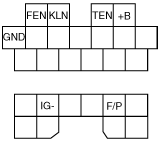
Terminal description
absggn00000320
|
|
Terminal |
Function |
Remark |
|
|---|---|---|---|
|
FEN
|
Outputs DTCs related to PCM
|
When using voltmeter
|
|
|
KLN
|
• Outputs DTCs related to PCM
• PID/DATA MONITOR AND RECORD function
• SIMULATION function
|
Mazda Modular Diagnostic System (M-MDS) communication line
|
|
|
TEN
|
Diagnostic test mode switching
|
Terminal grounded: Test mode
|
|
|
+B
|
B+
|
—
|
|
|
GND
|
Ground
|
—
|
|
|
IG–
|
Engine speed measurement
|
Connected to tachometer
|
|
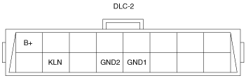
Data Link Connector-2 (DLC-2)
arnffn00000214
|
|
Terminal |
Function |
|---|---|
|
KLN
|
Serial communication KLN terminal
|
|
GND1
|
Body ground terminal
|
|
GND2
|
Serial communication ground terminal
|
|
B+
|
Battery power supply terminal
|