BALANCER SHAFT CONSTRUCTION/OPERATION [G6]
id011095112400
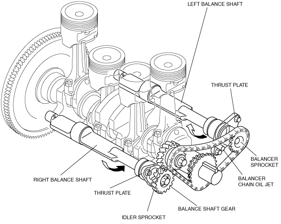
Construction
• Balance shafts are used to eliminate the secondary vertical vibrations created within the four-cylinder engine, reducing vibrations transmitted to the vehicle body.
• Two balance shafts are used in the G6 engine. The shafts are positioned on the same horizontal axis within the engine, and each is supported by three bushings of different sizes. The balance shafts and thrust plates are interchangeable left and right. The left balance shaft turns in the same direction as the crankshaft, while the right one turns opposite the crankshaft via the idler sprocket. Both balance shafts turn at twice the crankshaft speed.
Operation
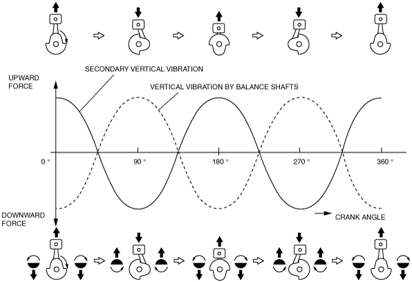
• In-line four-cylinder engines are normally constructed to have the pistons of the No.1 and No.4 cylinders moving in the opposite direction of those of the inner No.2 and No.3 cylinders. Therefore, the force generated by pistons No.1 and No.4 offsets the force generated by pistons No.2 and No.3.
• Due to the inertial weight of the piston/rod assemblies, however, different upward and downward forces are generated.
• Upward force is generated when the pistons are at TDC and BDC, and downward force is generated when the pistons are at the 90 ° and 270 ° crank angle position, which results in four vertical forces (two upward and two downward) each combustion cycle.
• This is known as secondary vertical vibration and can be quite severe at high engine speeds.
• The balance shafts offset this secondary vertical vibration by creating vibration of the same magnitude (as indicated by the dotted line) in the opposite direction.