 |
dbg110beb023
VALVE CLEARANCE INSPECTION [WL-C, WE-C]
id0110b6803400
1. Remove the engine cover.
2. Remove the following parts to turn the crankshaft.
3. Remove the fuel injector. (See FUEL INJECTOR REMOVAL/INSTALLATION [WL-C, WE-C].)
4. Remove the cylinder head cover.
5. Turn the crankshaft and align the timing mark so that the piston of the No. 1 or No. 4 cylinders is at TDC of compression.
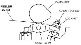
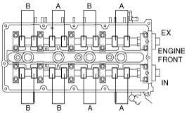
6. Measure valve clearances A with the No.1 cylinder at TDC of compression, and those of B with the No.4 cylinder at TDC of compression.
dbg110beb023
|
dbg110btbrr5
|
7. Turn the crankshaft one full turn and measure the remaining valve clearances. Adjust if necessary.
8. Install the cylinder head cover. (See CYLINDER HEAD GASKET REPLACEMENT [WL-C, WE-C].)
9. Install the fuel injector. (See FUEL INJECTOR REMOVAL/INSTALLATION [WL-C, WE-C].)
10. Install the water pump pulley, cooling fan and drive belt.
11. Adjust the drive belt deflection. (See DRIVE BELT ADJUSTMENT [WL-C, WE-C].)
12. Install the engine cover.