CRANKSHAFT POSITION (CKP) SENSOR INSPECTION [WL-C, WE-C]
id0140b7800500
-
Note
-
• Before performing the following inspection, make sure to follow the procedure as indicated in the troubleshooting flowchart.
Wave profile Inspection
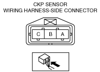
1. Measure the wave profile between CKP sensor connector terminal A—body ground, and CKP sensor connector terminal B—body ground.
-
• If not within the specification, replace the CKP sensor.
• If as specified, carry out the “Circuit Open/Short Inspection”.
Wave profile (Reference)
-
Oscilloscope setting
-
• 5 V/DIV (Y), 2 ms/DIV (X), DC range
-
Vehicle condition
-
• Idle after warm up
Circuit Open/Short Inspection
1. Disconnect the PCM connector. (See PCM REMOVAL/INSTALLATION [WL-C, WE-C].)
2. Inspect the following wiring harnesses for an open or short circuit. (Continuity check)
-
• if there is an open or short circuit, repair or replace wiring harnesses.
Open circuit
-
• Positive signal circuit (CKP sensor connector terminal A and PCM connector terminal 192)
• Negative signal circuit (CKP sensor connector terminal B and PCM connector terminal 193)
Short circuit
-
• CKP sensor connector terminal A and PCM connector terminal 192 short to power supply
• CKP sensor connector terminal A and PCM connector terminal 192 short to body ground
• CKP sensor connector terminal B and PCM connector terminal 193 short to power supply
• CKP sensor connector terminal B and PCM connector terminal 193 short to body ground