 |
absggw00000445
PCM INSPECTION [WL-C, WE-C]
id0140b7802500
Without Using the M-MDS
absggw00000445
|
Terminal voltage table (Reference)
|
Terminal |
Signal |
Connected to |
Test condition |
Voltage (V) |
Inspection item |
|
|---|---|---|---|---|---|---|
|
101
|
Fuel injector (#3)
|
Fuel injector No.3
|
Inspect using the wave profile.
|
• Inspect related wiring harness
• Fuel injector No.3
|
||
|
102
|
Fuel injector (#2)
|
Fuel injector No.2
|
Inspect using the wave profile.
|
• Inspect related wiring harness
• Fuel injector No.2
|
||
|
103
|
—
|
—
|
—
|
—
|
—
|
|
|
104
|
—
|
—
|
—
|
—
|
—
|
|
|
105
|
—
|
—
|
—
|
—
|
—
|
|
|
106
|
Constant voltage
|
EGR valve position sensor
|
Engine switch ON
|
Approx. 5
|
• Inspect related wiring harness
• EGR valve position sensor
|
|
|
107
|
—
|
—
|
—
|
—
|
—
|
|
|
108
|
—
|
—
|
—
|
—
|
—
|
|
|
109
|
Constant voltage
|
Fuel pressure sensor
|
Engine switch ON
|
Approx. 5
|
• Inspect related wiring harness
• Fuel pressure sensor
|
|
|
110
|
Ground
|
EGR valve position sensor
|
Under any condition
|
Below 1.0
|
• Inspect related wiring harness
• EGR valve position sensor
|
|
|
111
|
Ground
|
Boost/IAT sensor No.1
|
Under any condition
|
Below 1.0
|
• Inspect related wiring harness
• Boost/IAT sensor No.1
|
|
|
112
|
—
|
—
|
—
|
—
|
—
|
|
|
113
|
—
|
—
|
—
|
—
|
—
|
|
|
114
|
Ground
|
CMP sensor
|
Under any condition
|
Below 1.0
|
• Inspect related wiring harness
• CMP sensor
|
|
|
115
|
Fuel temp
|
Fuel temperature sensor
|
Engine switch ON
|
Fuel temperature
40 °C {104 °F}
|
Approx. 2.5
|
• Inspect related wiring harness
• Fuel temperature sensor
|
|
Fuel temperature
45 °C {113 °F}
|
Approx. 2.3
|
|||||
|
116
|
EGR position
|
EGR valve
|
Engine switch ON
|
Below 1.0
|
• Inspect related wiring harness
• EGR valve
|
|
|
EGR valve opening angle 40%
|
Approx. 2
|
|||||
|
117
|
—
|
—
|
—
|
—
|
—
|
|
|
118
|
—
|
—
|
—
|
—
|
—
|
|
|
119
|
—
|
—
|
—
|
—
|
—
|
|
|
120
|
—
|
—
|
—
|
—
|
—
|
|
|
121
|
—
|
—
|
—
|
—
|
—
|
|
|
122
|
—
|
—
|
—
|
—
|
—
|
|
|
123
|
—
|
—
|
—
|
—
|
—
|
|
|
124
|
—
|
—
|
—
|
—
|
—
|
|
|
125
|
Fuel injector (#1)
|
Fuel injector No.1
|
Inspect using the wave profile.
|
• Inspect related wiring harness
• Fuel injector No.1
|
||
|
126
|
Fuel injector (#4)
|
Fuel injector No.4
|
Inspect using the wave profile.
|
• Inspect related wiring harness
• Fuel injector No.4
|
||
|
127
|
—
|
—
|
—
|
—
|
—
|
|
|
128
|
A/C
|
A/C relay
|
A/C operating
|
Below 1.0
|
• Inspect related wiring harness
• A/C relay
|
|
|
A/C not operating
|
B+
|
|||||
|
129
|
Constant voltage
|
CMP sensor
|
Engine switch ON
|
Approx. 5
|
• Inspect related wiring harness
• CMP sensor
|
|
|
130
|
—
|
—
|
—
|
—
|
—
|
|
|
131
|
—
|
—
|
—
|
—
|
—
|
|
|
132
|
—
|
—
|
—
|
—
|
—
|
|
|
133
|
Constant voltage
|
Boost/IAT sensor No.1
|
Engine switch ON
|
Approx. 5
|
• Inspect related wiring harness
• Boost/IAT sensor No.1
|
|
|
134
|
—
|
—
|
—
|
—
|
—
|
|
|
135
|
neutral switch
|
Transfer neutral switch
|
Transfer shift lever neutral position
|
Below 1.0
|
• Inspect related wiring harness
• Transfer neutral switch
|
|
|
Except above
|
B+
|
|||||
|
136
|
—
|
—
|
—
|
—
|
—
|
|
|
137
|
4×4 indicator switch
|
4×4 indicator switch
|
Transfer shift lever 2H position
|
B+
|
• Inspect related wiring harness
• 4×4 indicator switch
|
|
|
Except above
|
Below 1.0
|
|||||
|
138
|
—
|
—
|
—
|
—
|
—
|
|
|
139
|
—
|
—
|
—
|
—
|
—
|
|
|
140
|
Fuel pressure
|
Fuel pressure sensor
|
Idle
|
Approx. 1.2
|
• Inspect related wiring harness
• Fuel pressure sensor
|
|
|
Engine speed is 2,800 rpm
|
Approx. 2.5
|
|||||
|
141
|
IAT
|
Boost/IAT sensor No.1
|
Engine switch ON
|
IAT 30 °C
{86 °F}
|
Approx. 1.4
|
• Inspect related wiring harness
• Boost/IAT sensor No.1
|
|
IAT 50 °C
{122 °F}
|
Approx. 1.2
|
|||||
|
142
|
—
|
—
|
—
|
—
|
—
|
|
|
143
|
—
|
—
|
—
|
—
|
—
|
|
|
144
|
—
|
—
|
—
|
—
|
—
|
|
|
145
|
—
|
—
|
—
|
—
|
—
|
|
|
146
|
—
|
—
|
—
|
—
|
—
|
|
|
147
|
—
|
—
|
—
|
—
|
—
|
|
|
148
|
—
|
—
|
—
|
—
|
—
|
|
|
149
|
Fuel injector (#2)
|
Fuel injector No.2
|
Inspect using the wave profile.
|
• Inspect related wiring harness
• Fuel injector No.2
|
||
|
150
|
Fuel injector (#4)
|
Fuel injector No.4
|
Inspect using the wave profile.
|
• Inspect related wiring harness
• Fuel injector No.4
|
||
|
151
|
—
|
—
|
—
|
—
|
—
|
|
|
152
|
Intake shutter solenoid valve (full close)
|
Intake shutter solenoid valve (full close)
|
Engine switch ON
|
B+
|
• Inspect related wiring harness
• Intake shutter solenoid valve (full close)
|
|
|
Idle
|
B+
(WL-C)
|
|||||
|
Below 1.0 (WE-C)
|
||||||
|
153
|
—
|
—
|
—
|
—
|
—
|
|
|
154
|
Ground
|
MAF/IAT sensor No.2
|
Under any condition
|
Below 1.0
|
• Inspect related wiring harness
• MAF/IAT sensor No.2
|
|
|
155
|
Intake shutter solenoid valve (half open)
|
Intake shutter solenoid valve (half open)
|
Engine switch ON
|
B+
|
• Inspect related wiring harness
• Intake shutter solenoid valve (half open)
|
|
|
156
|
Ground
|
ECT sensor
|
Under any condition
|
Below 1.0
|
• Inspect related wiring harness
• ECT sensor
|
|
|
157
|
—
|
—
|
—
|
—
|
—
|
|
|
158
|
—
|
—
|
—
|
—
|
—
|
|
|
159
|
—
|
—
|
—
|
—
|
—
|
|
|
160
|
CMP
|
CMP sensor
|
Inspect using the wave profile.
|
• Inspect related wiring harness
• CMP sensor
|
||
|
161
|
Idle
|
Idle switch
|
Engine switch On
|
B+
|
• Inspect related wiring harness
• Idle switch
|
|
|
Idle
|
Below 1.0
|
|||||
|
162
|
—
|
—
|
—
|
—
|
—
|
|
|
163
|
—
|
—
|
—
|
—
|
—
|
|
|
164
|
—
|
—
|
—
|
—
|
—
|
|
|
165
|
—
|
—
|
—
|
—
|
—
|
|
|
166
|
—
|
—
|
—
|
—
|
—
|
|
|
167
|
ECT
|
ECT sensor
|
Engine switch ON
|
ECT 30 °C
{86 °F}
|
Approx. 2.6
|
• Inspect related wiring harness
• ECT sensor
|
|
ECT 40 °C
{104 °F}
|
Approx. 2.1
|
|||||
|
ECT 50 °C
{122 °F}
|
Approx. 1.8
|
|||||
|
ECT 60 °C
{140 °F}
|
Approx. 1.4
|
|||||
|
168
|
—
|
—
|
—
|
—
|
—
|
|
|
169
|
Ground
|
MAF/IAT sensor No.2
|
Under any condition
|
Below 1.0
|
• Inspect related wiring harness
• MAF/IAT sensor No.2
|
|
|
170
|
Ground
|
Fuel temperature sensor
|
Under any condition
|
Below 1.0
|
• Inspect related wiring harness
• Fuel temperature sensor
|
|
|
171
|
CAN (L)
|
—
|
Because this terminal is for CAN, no valid determination of terminal voltage is possible
|
• Inspect related wiring harness
|
||
|
172
|
—
|
—
|
—
|
—
|
—
|
|
|
173
|
Fuel injector (#3)
|
Fuel injector No.3
|
Inspect using the wave profile.
|
• Inspect related wiring harness
• Fuel injector No.3
|
||
|
174
|
Fuel injector (#1)
|
Fuel injector No.1
|
Inspect using the wave profile.
|
• Inspect related wiring harness
• Fuel injector No.1
|
||
|
175
|
—
|
—
|
—
|
—
|
—
|
|
|
176
|
EGR solenoid valve
|
EGR solenoid valve
|
Engine switch ON
|
B+
|
• Inspect related wiring harness
• EGR solenoid valve
|
|
|
Idle
|
Approx. 3.5
|
|||||
|
177
|
EGR control solenoid valve
|
EGR control solenoid valve
|
Engine switch ON
|
B+
|
• Inspect related wiring harness
• EGR control solenoid valve
|
|
|
Idle
|
Below 1.0
|
|||||
|
178
|
VBC solenoid valve
|
VBC solenoid valve
|
Inspect using the wave profile.
|
• Inspect related wiring harness
• VBC solenoid valve
|
||
|
179
|
Fuel Metering Valve
|
Fuel Metering Valve
|
Inspect using the wave profile.
|
• Inspect related wiring harness
• Fuel Metering Valve
|
||
|
180
|
—
|
—
|
—
|
—
|
—
|
|
|
181*1
|
VSC solenoid valve
|
VSC solenoid valve
|
Engine switch ON
|
B+
|
• Inspect related wiring harness
• VSC solenoid valve
|
|
|
Idle (IAT at 13 °C {55 °F} or more, ECT at 10—70 °C {50—158 °F})
|
Below 1.0
|
|||||
|
182
|
Glow
|
Glow plug relay
|
13 s from when engine switch is turned to ON position with ECT at 20 °C {68 °F} or less
|
B+
|
• Inspect related wiring harness
• Glow plug relay
|
|
|
Idle (2m or more after engine is started)
|
Below 1.0
|
|||||
|
183
|
—
|
—
|
—
|
—
|
—
|
|
|
184
|
Vehicle speed
|
VSS
|
Inspect using the wave profile.
|
• Inspect related wiring harness
• VSS
|
||
|
185
|
RFW switch
|
RFW Switch
|
RFW “LOCK”
|
Below 1.0
|
• Inspect related wiring harness
• RFW switch
|
|
|
RFW “FREE”
|
B+
|
|||||
|
186
|
—
|
—
|
—
|
—
|
—
|
|
|
187
|
—
|
—
|
—
|
—
|
—
|
|
|
188
|
IAT
|
MAF/IAT sensor No.2
|
Engine switch ON
|
IAT 30 °C
{86 °F}
|
Approx. 1.9
|
• Inspect related wiring harness
• MAF/IAT sensor No.2
|
|
IAT 50 °C
{122 °F}
|
Approx. 1.2
|
|||||
|
189
|
MAP
|
Boost/IAT sensor No.1
|
Engine switch ON
|
Approx. 1.65
|
• Inspect related wiring harness
• Boost sensor
|
|
|
190
|
MAF
|
MAF/IAT sensor No.2
|
Engine switch ON
|
Below 1.0
|
• Inspect related wiring harness
• MAF/IAT sensor No.2
|
|
|
Idle
|
Approx. 1.76
|
|||||
|
191
|
Ground
|
Fuel pressure sensor
|
Under any condition
|
Below 1.0
|
• Inspect related wiring harness
• Fuel pressure sensor
|
|
|
192
|
CKP
|
CKP sensor
|
Inspect using the wave profile.
|
• Inspect related wiring harness
• CKP sensor
|
||
|
193
|
CKP
|
CKP sensor
|
Inspect using the wave profile.
|
• Inspect related wiring harness
• CKP sensor
|
||
|
194
|
Ground
|
CKP sensor
|
Under any condition
|
Below 1.0
|
• Inspect related wiring harness
• CKP sensor
|
|
|
195
|
CAN (H)
|
—
|
Because this terminal is for CAN, no valid determination of terminal
|
• Inspect related wiring harness
|
||
|
196
|
—
|
—
|
—
|
—
|
—
|
|
|
201
|
B+
|
Main relay
|
Main relay ON
|
B+
|
• Inspect related wiring harness
• Main relay
|
|
|
Main relay OFF
|
Below 1.0
|
|||||
|
202
|
Ground
|
Body ground
|
Under any condition
|
Below 1.0
|
• Inspect related wiring harness
|
|
|
203
|
B+
|
Main relay
|
Main relay ON
|
B+
|
• Inspect related wiring harness
• Main relay
|
|
|
Main relay OFF
|
Below 1.0
|
|||||
|
204
|
Ground
|
Body ground
|
Under any condition
|
Below 1.0
|
• Inspect related wiring harness
|
|
|
205
|
B+
|
Main relay
|
Main relay ON
|
B+
|
• Inspect related wiring harness
• Main relay
|
|
|
Main relay OFF
|
Below 1.0
|
|||||
|
206
|
Ground
|
Body ground
|
Under any condition
|
Below 1.0
|
• Inspect related wiring harness
|
|
|
207
|
—
|
—
|
—
|
—
|
—
|
|
|
208*2
|
Exhaust shutter solenoid valve
|
Exhaust shutter solenoid valve
|
Engine switch ON
|
B+
|
• Exhaust shutter solenoid valve
• Battery
• Inspect related wiring harness
|
|
|
Idle (warm up switch ON, intake air temperature less then 13 °C {55 °F}, engine coolant temperature less then 80 °C {176 °F}, engine speed less then 1,420 rpm)
|
Below 1.0
|
|||||
|
209
|
APP
|
APP sensor
|
Accelerator pedal released
|
Below 1.0
|
• Inspect related wiring harness
• APP sensor
|
|
|
Accelerator pedal depressed
|
Approx. 3.6
|
|||||
|
210
|
—
|
—
|
—
|
—
|
—
|
|
|
211
|
—
|
—
|
—
|
—
|
—
|
|
|
212
|
Ground
|
APP sensor
|
Under any condition
|
Below 1.0
|
• Inspect related wiring harness
• APP sensor
|
|
|
213
|
Constant voltage
|
APP sensor
|
Engine switch ON
|
Approx. 5
|
• Inspect related wiring harness
• APP sensor
|
|
|
214
|
—
|
—
|
—
|
—
|
—
|
|
|
215
|
—
|
—
|
—
|
—
|
—
|
|
|
216
|
—
|
—
|
—
|
—
|
—
|
|
|
217
|
—
|
—
|
—
|
—
|
—
|
|
|
218
|
—
|
—
|
—
|
—
|
—
|
|
|
219
|
Main relay control
|
Main relay
|
Engine switch ON
|
Below 1.0
|
• Inspect related wiring harness
• Main relay
|
|
|
Engine switch OFF
|
B+
|
|||||
|
220
|
—
|
—
|
—
|
—
|
—
|
|
|
221
|
—
|
—
|
—
|
—
|
—
|
|
|
222
|
APP
|
APP sensor
|
Accelerator pedal released
|
Below 1.0
|
• Inspect related wiring harness
• APP sensor
|
|
|
Accelerator pedal depressed
|
Approx. 3.6
|
|||||
|
223
|
—
|
—
|
—
|
—
|
—
|
|
|
224
|
—
|
—
|
—
|
—
|
—
|
|
|
225
|
IG 1
|
Engine switch
|
Engine switch is ON and Start position
|
B+
|
• Inspect related wiring harness
|
|
|
Engine switch is other position
|
Below 1.0
|
|||||
|
226
|
Diagnostic test mode
|
Data link connector (DLC) (Terminal TEN)
|
Engine switch ON
|
Open terminal TEN
|
B+
|
• Inspect related wiring harness
|
|
Short terminal TEN
|
Below 1.0
|
|||||
|
227
|
Glow system
|
Glow relay
|
ECT is below 60 °C {140 °F}
|
For less than approx. 13 seconds after turning engine switch ON.
|
B+
|
• Inspect related wiring harness
• Glow relay
|
|
Over approx. 13 seconds after turning engine switch ON.
|
Below 1.0
|
|||||
|
For less than 2 minutes starting engine.
|
B+
|
|||||
|
Over 2 minutes after starting engine.
|
Below 1.0
|
|||||
|
While cranking
|
B+
|
|||||
|
ECT is above 60 °C {140 °F}
|
For less than approx. 4 seconds after turning engine switch ON.
|
B+
|
||||
|
Over approx. 4 seconds after turning engine switch ON.
|
Below 1.0
|
|||||
|
While cranking
|
Below 1.0
|
|||||
|
228
|
Clutch
|
CPP switch
|
Clutch pedal released
|
B+
|
• Inspect related wiring harness
• CPP switch
|
|
|
Clutch pedal depressed
|
Below 1.0
|
|||||
|
229
|
—
|
—
|
—
|
—
|
—
|
|
|
230
|
Coil
(Immobilizer system)
|
Immobilizer-related information
|
No valid determination of terminal voltage is possible
|
• Inspect related wiring harness
|
||
|
231
|
DTC output
|
Data link connector (DLC) (Terminal TEN)
|
No DTC output
|
B+
|
• Inspect related wiring harness
|
|
|
DTC output
|
Below 1.0
|
|||||
|
232
|
4×4 indicator light
|
4×4 indicator light
|
4×4 indicator light OFF
|
Below 1.0
|
• Inspect related wiring harness
• Instrument cluster (4×4 indicator light)
|
|
|
4×4 indicator light ON
|
B+
|
|||||
|
233
|
Glow indicator light
|
Glow indicator light
|
Engine switch OFF
|
Below 1.0
|
• Inspect related wiring harness
• Glow indicator light
|
|
|
Engine switch is ON and within approx. 0.5 sec. (25 °C {77 °F})
|
||||||
|
Over 0.5 seconds (25 °C {77 °F}) after turning engine switch ON
|
B+
|
|||||
|
234
|
—
|
—
|
—
|
—
|
—
|
|
|
235
|
IG 1
|
Engine fuse
|
Engine switch ON
|
B+
|
• Inspect related wiring harness
• Engine fuse
|
|
|
236*2
|
Warm up switch
|
Warm up switch
|
Engine switch ON
|
Warm up switch ON
|
B+
|
• Warm up switch
• Inspect related wiring harness
|
|
Warm up switch OFF
|
Below 1.0
|
|||||
|
237
|
—
|
—
|
—
|
—
|
—
|
|
|
238
|
Brake light
|
Brake light
|
brake pedal released
|
Below 1.0
|
• Inspect related wiring harness
• Brake light
|
|
|
brake pedal depressed
|
B+
|
|||||
|
239
|
Thermo
|
Thermo switch
|
A/C operating
|
Below 1.0
|
• Inspect related wiring harness
• Thermo switch
|
|
|
A/C not operating
|
B+
|
|||||
|
240
|
Neutral
|
Neutral switch
|
Shift lever neutral position
|
Below 1.0
|
• Inspect related wiring harness
• Neutral switch
|
|
|
Except shift lever neutral position
|
B+
|
|||||
|
241
|
—
|
—
|
—
|
—
|
—
|
|
|
242
|
—
|
—
|
—
|
—
|
—
|
|
|
243
|
—
|
—
|
—
|
—
|
—
|
|
|
244
|
RFW indicator light
|
LOCK indicator light
|
LOCK indicator light OFF
|
B+
|
• Inspect related wiring harness
• Instrument cluster (LOCK indicator light)
|
|
|
LOCK indicator light ON
|
Below 1.0
|
|||||
|
245
|
—
|
—
|
—
|
—
|
—
|
|
|
246
|
—
|
—
|
—
|
—
|
—
|
|
|
247
|
—
|
—
|
—
|
—
|
—
|
|
|
248
|
—
|
—
|
—
|
—
|
—
|
|
|
249
|
—
|
—
|
—
|
—
|
—
|
|
|
250
|
—
|
—
|
—
|
—
|
—
|
|
|
251
|
—
|
—
|
—
|
—
|
—
|
|
|
252
|
—
|
—
|
—
|
—
|
—
|
|
|
253
|
Lock solenoid valve
|
Lock solenoid valve
|
Lock solenoid valve operating
|
Below 1.0
|
• Inspect related wiring harness
• Lock solenoid valve
|
|
|
Lock solenoid valve not operating
|
B+
|
|||||
|
254
|
Free solenoid valve
|
Free solenoid valve
|
Free solenoid valve operating
|
Below 1.0
|
• Inspect related wiring harness
• Free solenoid valve
|
|
|
Free solenoid valve not operating
|
B+
|
|||||
|
255
|
—
|
—
|
—
|
—
|
—
|
|
|
256
|
MIL
|
Malfunction indicator light
|
Malfunction indicator light ON
|
Below 1.0
|
• Inspect related wiring harness
• Malfunction indicator light
|
|
|
Malfunction indicator light OFF
|
B+
|
|||||
|
257
|
—
|
—
|
—
|
—
|
—
|
|
|
258
|
RFW main switch
|
RFW main switch
|
RFW main switch released (OFF)
|
B+
|
• Inspect related wiring harness
• RFW main switch
|
|
|
RFW main switch depressed (ON)
|
Below 1.0
|
|||||
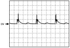
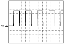
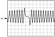
Inspection Using An Oscilloscope (Reference)
Fuel injector signal
absggw00000446
|
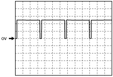
CMP signal
absggw00000447
|
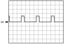
VBC solenoid valve signal
absggw00000448
|
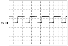
Fuel Metering Valve signal
absggw00000449
|
Vehicle speed signal
absggw00000450
|
CKP signal
absggw00000451
|
Using the M-MDS
1. Connect the M-MDS to the DLC-2. (See ON-BOARD DIAGNOSTIC TEST [WL-C, WE-C].)
2. Measure the PID value.
3. Turn the engine switch to the ON position (Engine off).
PID Monitor Table (Reference)
|
Monitor item (Definition) |
Unit/Condition |
Condition/Specification (Reference) |
Inspection item |
PCM terminal |
||||||
|---|---|---|---|---|---|---|---|---|---|---|
|
AAT
(Ambient temperature)
|
°C
|
Ambient temperature
|
—
|
|||||||
|
AC_REQ
(A/C request signal)
|
On/Off
|
Refrigerant pressure switch is off: Off
Others: On
|
A/C switch
|
239
|
||||||
|
ACCS
(Air conditioning compressor cycling switch)
|
On/Off
|
A/C switch ON and fan switch ON: On
Others: Off
|
Inspect following PIDs: START_SW, CPP, CPP/PNP, IVS, AC_REQ, APS1, APS2, ECT, RPM
|
128
|
||||||
|
APP
(Accelerator pedal position)
|
%
|
Accelerator pedal released: 0 % Accelerator pedal depressed: 100 %
|
Inspect following PIDs: APP1, APP2
|
209, 222
|
||||||
|
APP1
(Accelerator pedal position sensor No.1)
|
%
|
Accelerator pedal released: 0%
Accelerator pedal depressed: 100%
|
APP sensor
|
222
|
||||||
|
V
|
Accelerator pedal released:
Below 1.0 V
Accelerator pedal depressed:
Approx. 3.6 V
|
|||||||||
|
APP2
(Accelerator pedal position sensor No.2)
|
%
|
Accelerator pedal released: 0%
Accelerator pedal depressed: 100%
|
APP sensor
|
209
|
||||||
|
V
|
Accelerator pedal released:
Below 1.0 V
Accelerator pedal depressed:
Approx. 3.6 V
|
|||||||||
|
ARPMDES
(Target engine speed)
|
RPM
|
No load: 695—745 rpm
A/C ON: 725—775 rpm
|
Inspect following PIDs:
IVS, AC_REQ, IAT, IAT2, ECT, BOOST_DSD, FRP, FRP_A, RPM, VSS
|
—
|
||||||
|
BARO
(Barometric pressure)
|
kPa
|
Bar
|
psi
|
Indicate Barometric pressure
|
BARO sensor
|
—
|
||||
|
V
|
BARO 103 kPa {1.03 Bar, 14.9 psi}: Approx. 4.0 V
|
|||||||||
|
BOO
(Brake switch)
|
On/Off
|
Brake pedal released: Off
Brake pedal depressed: On
|
Brake switch
|
238
|
||||||
|
CPP
(CPP switch)
|
On/Off
|
Clutch pedal released: On
Clutch pedal depressed: Off
|
CPP switch
|
228
|
||||||
|
DTCCNT
(DTC count)
|
—
|
Number of DTCs stored in the PCM is displayed.
|
Perform applicable DTC troubleshooting.
|
—
|
||||||
|
ECT
(Engine coolant temperature)
|
°C
|
Engine coolant temperature is displayed
|
Inspect ECT sensor.
|
167
|
||||||
|
V
|
ECT 30 °C {86 °F}: Approx. 2.6 V
ECT 40 °C {104 °F}: Approx. 2.1 V
ECT 50 °C {122 °F}: Approx. 1.8 V
ECT 60 °C {140 °F}: Approx. 1.4 V
|
|||||||||
|
EGRV2
(EGR control solenoid valve)
|
On/Off
|
Engine switch ON: ON
Idle: OFF
|
Inspect EGR control solenoid valve
|
177
|
||||||
|
FIP_FL
(Supply pump flow control)
|
A
|
Engine switch ON: 1.35 A
Idle: Approx. 1.45 A
|
Inspect following PIDs:
IVS, AC_REQ, IAT1, IAT2, ECT, BOOST_DSD, FRP, FRP_A, RPM, VSS
|
179
|
||||||
|
%
|
Engine switch ON: 14.6 %
Idle: 37.6 %
|
|||||||||
|
FIP_SCV
(Fuel metering valve)
|
A
|
Engine switch ON: Approx. 580 mA
Idle: 1.45 A
|
Inspect following PIDs:
IVS, AC_REQ, IAT1, IAT2, ECT, BOOST_DSD, FRP, FRP_A, RPM, VSS
|
179
|
||||||
|
FLT
(Fuel temperature)
|
°C
|
Fuel temperature is displayed.
|
Fuel temperature sensor
|
115
|
||||||
|
FRP
(Fuel pressure sensor)
|
kPa
|
Bar
|
psi
|
Engine switch ON: 0 kPa {0 psi, 0 Bar}
|
Fuel pressure sensor
|
140
|
||||
|
Idle: Approx. 32 MPa
2,000 rpm: Approx. 58 MPa {580 Bar, 8,412 psi}
|
||||||||||
|
GP_LMP
(Glow indicator light)
|
On/Off
|
Glow indicator light Off: Off
Glow indicator light ON: On
|
Inspect following PIDs:
ECT, BOOST_DSD, VSS
|
233
|
||||||
|
GPC
(Glow plug relay)
|
On/Off
|
13s from when engine switch is turned to ON position with ECT at 20 °C{68 °F} of less
|
182
|
|||||||
|
Cranking: On (ECT at 60 °{140 °F} or less)
Idle: Off (2m or more after engine is started)
|
||||||||||
|
IASV
(Intake shutter solenoid valve (full close))
|
On/Off
|
Engine switch ON: OFF
Idle: OFF
|
Intake air shutter valve
|
152
|
||||||
|
IASV2
(Intake shutter solenoid valve (half open))
|
On/Off
|
Engine switch ON: OFF
|
155
|
|||||||
|
IAT
(Intake air temperature (IAT sensor No.1))
|
V
|
30 °C {86 °F}: Approx. 1.4 V
50 °C {104 °F}: Approx. 1.2 V
|
IAT sensor
|
141
|
||||||
|
°C
|
Intake air temperature is display
|
|||||||||
|
INGEAR
(Load/no load condition)
|
On/Off
|
Neutral: On
Others: Off
|
Inspect following PIDs: CPP
|
240
|
||||||
|
IVS
(Idle switch)
|
Idle/Off Idle
|
CTP: Idle
Others: Off Idle
|
APP sensor
|
161
|
||||||
|
LOAD
(Engine load)
|
%
|
Engine switch ON: 0%
Idle: Approx. 22 %
|
MAF sensor
|
—
|
||||||
|
MAF
(Mass airflow amount)
|
g/s
|
Engine switch ON: 2 g/s
Idle: Approx. 8 g/s
|
MAF sensor
|
190
|
||||||
|
V
|
Engine switch ON: Below 1.0 V
Idle: Approx. 1.76 V
|
|||||||||
|
MAP
(Boost sensor)
|
kPa
|
Bar
|
psi
|
Manifold absolute pressure is displayed
|
MAP sensor
|
189
|
||||
|
V
|
Engine switch ON: Approx. 1.65 V
Idle: Approx. 1.65 V
|
|||||||||
|
MIL
(Malfunction indicator lamp)
|
On/Off
|
Engine switch ON: On
|
Perform applicable DTC troubleshooting.
|
256
|
||||||
|
Idle: Off
|
||||||||||
|
MIL_DIS
(The distance travelled since the MIL was activated)
|
Km
|
Indicate the travelled distance since the MIL illuminated
|
—
|
|||||||
|
RPM
(Engine speed)
|
rpm
|
Engine switch ON: 0 RPM
|
CKP sensor
|
193
|
||||||
|
Idle
|
No load: 695—745 rpm
A/C ON: 725—775 rpm
|
|||||||||
|
SEGRP DSD
(Desired EGR valve position)
|
%
|
Engine switch ON: Approx. 4.68 %
Idle: Approx. 78 %
Engine speed 2,000 rpm: Approx. 94 %
|
Desired SEGRP valve position
|
—
|
||||||
|
SELTESTDTC (Diagnostic trouble codes)
|
—
|
—
|
Perform applicable DTC troubleshooting
|
—
|
||||||
|
SCV
(VSC solenoid valve)
|
On/Off
|
Engine switch ON: OFF
Idle: (IAT at 13 °C {55 °F} or more, ECT at 10—70 °C {50—158 °F}): ON
|
VSC solenoid valve
|
181
|
||||||
|
VBCV
(VBC solenoid valve)
|
%
|
Engine switch ON: Approx. 4.99 %
Idle: Approx. 79 %
|
Inspect following PIDs: IVS, MAF, ECT, RPM
Inspect VBC solenoid valve.
|
178
|
||||||
|
VPWR
(Module supply voltage)
|
V
|
Indicate the battery positive voltage
|
Battery
Main relay
|
201, 203, 205
|
||||||
|
VSS
(Vehicle speed)
|
km/h
|
Vehicle speed is displayed
|
Perform applicable DTC troubleshooting.
|
184
|
||||||