 |
absggw00001667
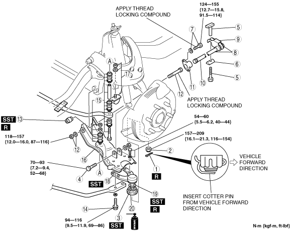
TORSION BAR SPRING AND LOWER ARM REMOVAL/INSTALLATION [4x2 (EXCEPT HIGH CLEARANCE MODEL)]
id0213008030a3
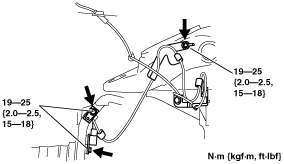
1. Remove the ABS sensor wiring harness brackets installed to the upper arm and steering knuckle, then move aside the ABS sensor.
absggw00001667
|
2. Remove in the order indicated in the table.
3. Install in the reverse order of removal.
4. Inspect the vehicle height and adjust it if necessary. (See VEHICLE HEIGHT ADJUSTMENT [4x2].)
5. Inspect the front wheel alignment and adjust it if necessary. (See FRONT WHEEL ALIGNMENT [4x2].)
absggw00001668
|
|
1
|
Cotter pin
|
|
2
|
Nut
|
|
3
|
Front lower arm ball joint
|
|
4
|
Shock absorber lower bolt and nut
|
|
5
|
Anchor bolt
(See Anchor Bolt Removal Note.)
|
|
6
|
Anchor swivel
|
|
7
|
Bolt and washer
|
|
8
|
Torsion bar component
|
|
9
|
Anchor arm
|
|
10
|
Torsion bar spring
|
|
11
|
Torque plate
|
|
12
|
Lower arm spindle, washer, and nut
|
|
13
|
Rubber bushing
(See Rubber Bushing Removal Note.)
|
|
14
|
Tension rod bolt
|
|
15
|
Stabilizer bolt, bushing, retainer, spacer, and nut
|
|
16
|
Front lower arm
|
|
17
|
Bound stopper
|
|
18
|
Front lower arm ball joint
|
|
19
|
Clip
(See Clip Installation Note.)
|
|
20
|
Dust boot
|
|
21
|
Clip
(See Clip Installation Note.)
|
|
22
|
Dust boot
|
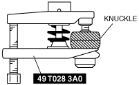
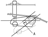
Front Lower Arm Ball Joint Removal Note
1. Separate the ball joint from the knuckle arm using the SST.
absggw00001669
|
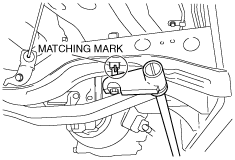
Anchor Bolt Removal Note
1. Mark the anchor bolt and swivel for reference during installation.
absggw00001670
|
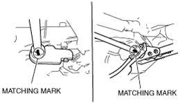
Torsion Bar Spring Removal Note
1. Mark the torsion bar spring, anchor arm, the torsion bar spring and torque plate for reference during installation.
absggw00001671
|
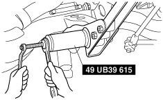
Rubber Bushing Removal Note
1. Remove the rubber bushing from the body using the SST.
absggw00001672
|
Clip Installation Note
1. Install the SST to the ball joint stud with the stud stands straight up.
absggw00001673
|
2. Install the clip in the dust boot groove.
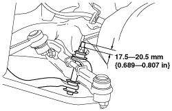
Stabilizer Bolt, Bushing, Retainer, Spacer, And Nut Installation Note
1. Tighten the nuts so that 17.5—20.5 mm {0.689—0.807 in} of thread is exposed at the end of the bolt.
absggw00001674
|
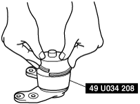
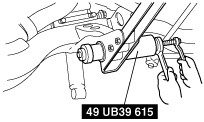
Rubber Bushing Installation Note
1. Install a new bushing using the SST.
absggw00001675
|
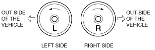
Torsion Bar Spring Installation Note
1. Before installation, check the identification mark on the end of the torsion bar spring.
absggw00001676
|
2. Align the marks made during removal, and connect the torsion bar spring to the torque plate.
absggw00001671
|
Anchor Bolt Installation Note
1. Install the anchor bolt, and tighten it until the marks made during removal are aligned.
absggw00001670
|
absggw00001677
|