|
absggw00000144
TRANSMISSION REMOVAL/INSTALLATION [S15M-D]
id0511c1246700
1. Disconnect the negative battery cable.
2. Remove the propeller shaft. (See PROPELLER SHAFT REMOVAL/INSTALLATION [MT].)
3. Remove the front pipe and oxidation catalytic converter. (See EXHAUST SYSTEM REMOVAL/INSTALLATION [WL-C, WE-C].)
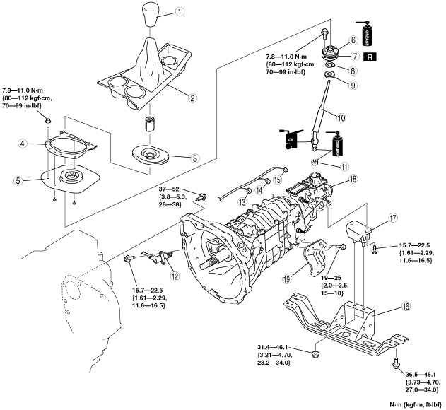
4. Remove in the order indicated in the table.
5. Install in the reverse order of removal.
6. Perform the "INSPECTION AFTER TRANSMISSION INSTALLATION", and verify that there is no abnormality.
(See INSPECTION AFTER TRANSMISSION INSTALLATION [S15M-D].)
7. If the transmission for a type A vehicle is newly replaced, perform PCM reprogramming. (See PCM REPROGRAMMING [WL-C, WE-C].)
|
Type A vehicle: Applied VIN (assumed)
|
|
JMZ UN1***** 800001—JMZ UN1***** 833762
|
|
MM0 UN****** 800001—MM0 UN****** 834176
|
|
MM6 UN****** 800001—MM6 UN****** 834176
|
|
MM7 UN2***** 800001—MM7 UN2***** 834159
|
|
MM7 UN3***** 800001—MM7 UN3***** 834159
|
|
MM7 UNY0**** 800001—MM7 UNY0**** 834176
|
Except high clearance model
absggw00000144
|
|
1
|
Shift lever knob
|
|
2
|
Console (regular cab) or boot panel (except regular cab)
(See CONSOLE REMOVAL/INSTALLATION.)
|
|
3
|
Dust boot
|
|
4
|
Change boot upper plate
|
|
5
|
Boot
|
|
6
|
Dust boot
|
|
7
|
Gasket
|
|
8
|
Wave washer
|
|
9
|
Change bush
|
|
10
|
Shift lever
|
|
11
|
Change seat
|
|
12
|
Clutch release cylinder
|
|
13
|
Neutral switch connector
|
|
14
|
Back-up light switch connector
|
|
15
|
Vehicle speed sensor connector
|
|
16
|
Crossmember
|
|
17
|
Bolt
|
|
18
|
Bolt
|
|
19
|
Transmission mount rubber
|
|
20
|
Transmission mount bracket
|
|
21
|
Transmission
|
|
22
|
Front pipe bracket
|
High clearance model
absggw00000145
|
|
1
|
Shift lever knob
|
|
2
|
Boot panel
(See CONSOLE REMOVAL/INSTALLATION.)
|
|
3
|
Dust boot
|
|
4
|
Change boot upper plate
|
|
5
|
Boot
|
|
6
|
Dust boot
|
|
7
|
Gasket
|
|
8
|
Wave washer
|
|
9
|
Change bush
|
|
10
|
Shift lever
|
|
11
|
Change seat
|
|
12
|
Clutch release cylinder
|
|
13
|
Neutral switch connector
|
|
14
|
Back-up light switch connector
|
|
15
|
Vehicle speed sensor connector
|
|
16
|
Crossmember
|
|
17
|
Transmission mount rubber
|
|
18
|
Transmission
|
|
19
|
Front pipe bracket
|
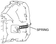
Crossmember Removal Note [Except High Clearance Model]
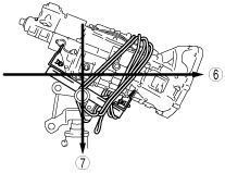
1. Remove the front parking brake cable as shown in the figure. (See PARKING BRAKE CABLE REMOVAL/INSTALLATION [WL-C (4x2 EXCEPT HIGH CLEARANCE MODEL)].)
absggw00000146
|
absggw00000147
|
2. Remove the crossmember.
Transmission Removal/installation Note
absggw00001252
|
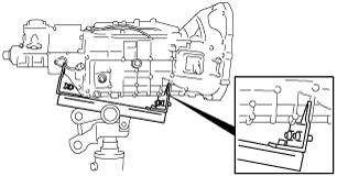
1. Support the transmission securely using a transmission jack.
2. Set the transmission jack attachment into the concavity of the transmission to prevent the transmission from falling when it is tilted.
absggw00000149
|
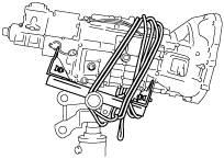
3. Remove the following parts:
4. Remove the transmission installation bolt.
5. Remove the transmission.
absggw00000150
|
absggw00000151
|
absggw00000152
|
6. Install in the reverse order of removal.
Shift Lever Component Installation Note
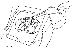
1. Add the specified type and amount of oil to the shift control case.
absggw00000153
|