 |
absggw00001183
SOLENOID VALVE INSPECTION [5R55S]
id0513c1253200
1. Disconnect the negative battery cable.
2. Remove the digital TR sensor insulator.
3. Remove the CKP sensor insulator.
4. Remove the insulator bracket.
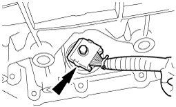
5. Disconnect the AT connector.
absggw00001183
|
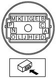
6. Measure the resistance between the following terminals.
absggw00001184
|
Solenoid valve resistance
|
Terminals |
Solenoid valve |
Resistance (ohm) |
|---|---|---|
|
D—I
|
Shift solenoid A
|
16—45
|
|
F—I
|
Shift solenoid B
|
16—45
|
|
B—I
|
Shift solenoid C
|
16—45
|
|
E—I
|
Shift solenoid D
|
16—45
|
|
O—I
|
Pressure control solenoid A
|
3.3—7.5
|
|
M—I
|
Pressure control solenoid B
|
3.3—7.5
|
|
G—I
|
Pressure control solenoid C
|
3.3—7.5
|
|
H—I
|
TCC control solenoid
|
9—16
|
7. Connect the AT connector.
8. Remove the insulator bracket. (See AUTOMATIC TRANSMISSION REMOVAL/INSTALLATION [5R55S].)
9. Remove the CKP sensor insulator. (See AUTOMATIC TRANSMISSION REMOVAL/INSTALLATION [5R55S].)
10. Remove the digital TR sensor insulator. (See AUTOMATIC TRANSMISSION REMOVAL/INSTALLATION [5R55S].)
11. Connect the negative battery cable.