 |
absggw00001811
DIGITAL TRANSMISSION RANGE (TR) SENSOR ADJUSTMENT [5R55S]
id0513c1254900
1. Disconnect the negative battery cable.
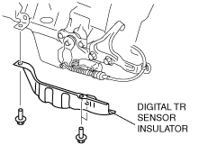
2. Remove the digital TR sensor insulator.
absggw00001811
|
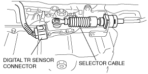
3. Disconnect the digital TR sensor connector.
absggw00001813
|
4. Remove the selector cable.
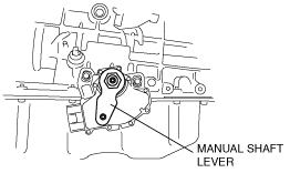
5. Rotate the manual shaft to the N position.
6. Set the adjustable wrench as shown in the figure to hold the manual shaft lever.
absggw00001032
|
7. Remove the manual shaft nut.
8. Remove the manual shaft lever.
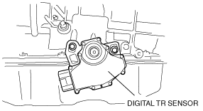
9. Loosen the digital TR sensor mounting bolts.
absggw00001814
|
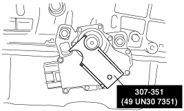
10. Using the SST, align the digital TR sensor and tighten the screws in an alternating sequence.
absggw00001035
|
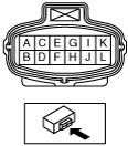
11. Inspect for continuity between digital TR sensor terminals A, E and I.
absggw00001017
|
12. Install the manual shaft lever.
absggw00001032
|
13. Set the adjustable wrench as shown in the figure to hold the manual shaft lever.
14. Tighten the manual shaft nut using a torque wrench.
15. Shift the selector lever to P position.
16. Turn the manual shaft lever to P position.
17. Install the selector cable.
absggw00001813
|
18. Connect the digital TR sensor connector.
19. Install the digital TR sensor insulator.
absggw00001811
|
20. Connect the negative battery cable.
21. Inspect digital TR sensor operation. (See DIGITAL TRANSMISSION RANGE (TR) SENSOR INSPECTION [5R55S].)