 |
b5r5za00000268
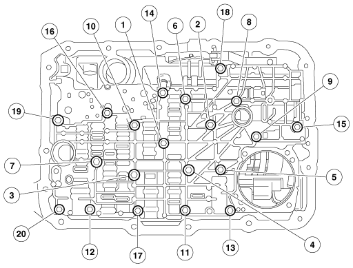
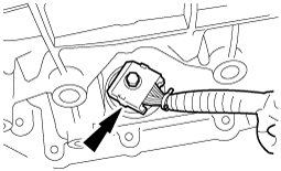
CONTROL VALVE BODY INSTALLATION [5R55S]
id0513c1710700
On-Vehicle Installation
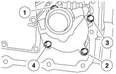
1. Install the control valve body and loosely install the bolts.
b5r5za00000268
|
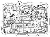
2. Tighten the bolts in the sequence shown.
b5r5za00000270
|
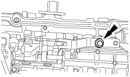
3. Install the detent spring.
b5r5za00000271
|
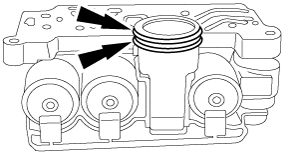
4. Install new O-rings on the solenoid body connector. Lubricate the O-rings with clean ATF.
b5r5za00000272
|
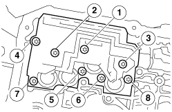
5. Install the solenoid body. Tighten bolts in the sequence shown.
b5r5za00000273
|
6. Install the reverse servo. Tighten the bolts in the sequence shown in 2 stages.
b5r5za00000274
|
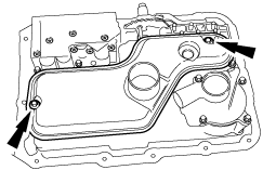
7. Lubricate the seals and install the transmission fluid filter.
b5r5za00000275
|
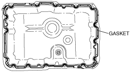
8. Install the transmission fluid pan gasket on the pan.
absggw00001562
|
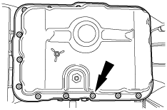
9. Install the transmission fluid pump and gasket, magnet and loosely install the bolts.
b5r5za00000276
|
10. Tighten the bolts in a crisscross sequence.
11. Install and lubricate new O-rings on the AT connector and connect the connector.
absggw00001183
|
12. Remove the insulator bracket. (See AUTOMATIC TRANSMISSION REMOVAL/INSTALLATION [5R55S].)
13. Remove the CKP sensor insulator. (See AUTOMATIC TRANSMISSION REMOVAL/INSTALLATION [5R55S].)
14. Remove the digital TR sensor insulator. (See AUTOMATIC TRANSMISSION REMOVAL/INSTALLATION [5R55S].)
15. Connect the negative battery cable.
16. Add ATF and, with the engine idling, inspect the ATF level and for leakage. (See AUTOMATIC TRANSMISSION FLUID (ATF) INSPECTION [5R55S].)
17. Perform the mechanical system test. (See MECHANICAL SYSTEM TEST [5R55S].)
18. Perform the road test. (See ROAD TEST [5R55S].)