 |
absggw00001210
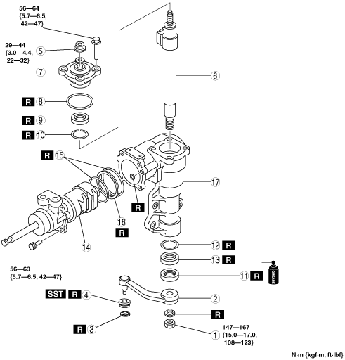
STEERING GEAR AND LINKAGE DISASSEMBLY/ASSEMBLY
id061400803300
1. Disassemble in the order indicated in the table.
2. Assemble in the reverse order of disassembly.
3. After assembly, adjust the steering gear backlash. (See STEERING GEAR AND LINKAGE INSPECTION.)
absggw00001210
|
|
1
|
Nut
|
|
2
|
Pitman arm
(See Pitman Arm Disassembly Note.)
|
|
3
|
Clip
|
|
4
|
Dust boot
(See Dust Boot Disassembly Note.)
(See Dust Boot Assembly Note.)
|
|
5
|
Locknut
|
|
6
|
Sector shaft
|
|
7
|
Side cover
|
|
8
|
O-ring
|
|
9
|
Back up ring
|
|
10
|
Y packing
|
|
11
|
Oil seal
|
|
12
|
Y packing
|
|
13
|
Back up ring
|
|
14
|
Valve and piston component
|
|
15
|
O-ring
|
|
16
|
Seal ring
|
|
17
|
Gear housing
|
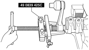
Pitman Arm Disassembly Note
1. Separate the pitman arm from the steering gear using the SST.
absggw00002284
|
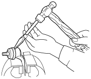
Dust Boot Disassembly Note
1. Place the chisel against the boot and hold it at the angle shown.
2. Remove the dust boot by tapping it with a hammer.
absggw00001212
|
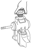
Locknut, Sector Shaft Disassembly Note
1. Loosen the locknut.
2. Remove the side cover attaching bolts.
3. Set the sector shaft in the middle position.
4. Tap the sector shaft lower end using a plastic hammer to loosen the sector shaft.
5. Lift and remove the sector shaft with the locknut and the side cover from the gear housing.
absggw00001213
|
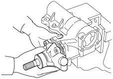
Valve and Piston Component Assembly Note
1. Insert the valve and piston component to the gear housing.
absggw00001214
|
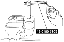
2. Inspect the worm shaft preload using the SST.
absggw00001215
|
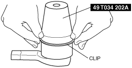
Dust Boot Assembly Note
1. Wipe the grease off the ball joint.
2. Put a small amount of lithium-based grease into a new dust boot.
3. Install the dust boot onto to the ball joint.
4. Set the SST over the boot and install a new clip.
absggw00001216
|
5. Wipe away excessive grease.