|
dbg740zwb699
A/C AMPLIFIER INSPECTION
id074000830200
1. Connect the A/C amplifier connector.
2. Turn the engine switch to the ON position.
3. Connect the negative (-) lead of the tester to body ground.
4. By inserting the positive (+) lead of the tester into each A/C amplifier terminal, measure the voltage according to the terminal voltage table.
Terminal Voltage Table
dbg740zwb699
|
|
Terminal |
Signal name |
Connected to |
Measurement condition |
Voltage (V) |
Inspection item (s) |
|---|---|---|---|---|---|
|
1A
|
IG2
|
A/C2 10 A fuse
|
Engine switch at ON position
|
B+
|
• Inspect for continuity or short circuit (A/C amplifier—A/C2 10 A fuse:1A—A/C2 10 A fuse
• Inspect A/C2 10 A fuse
|
|
Engine switch at LOCK position
|
Below 1.0
|
• Inspect short circuit (A/C amplifier—A/C2 10 A fuse:1A—A/C2 10 A fuse)
|
|||
|
1B
|
A/C
|
A/C relay
|
A/C switch OFF
|
B+
|
• Inspect or continuity or short circuit (A/C amplifier—A/C relay:1B—Inspect A/C relay
|
|
A/C switch ON
|
Below 1.0
|
• Inspect terminal voltage of A/C amplifier (1A)
|
|||
|
1C
|
GND
|
Ground
|
Under any condition
|
Below 1.0
|
• Inspect for continuity (A/C amplifier—ground:1C—GND)
|
Thermistor Side
1. Connect the thermistor connector.
2. Turn the engine switch to the ON position.
3. Turn the fan switch ON.
4. Turn the A/C switch ON.
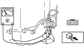
5. Connect the positive (+) probe of the voltmeter to terminal 2A of the thermistor connector and the negative (-) probe to terminal 2B. (The wiring harness connector must be connected to the thermistor connector.)
dbg740zwb600
|
6. If there is any malfunction, replace the A/C amplifier.