|
1
|
INSPECT DRIVER‐SIDE AIR BAG MODULE CONNECTOR (CLOCK SPRING)
-
Warning
-
• Handling the air bag system components improperly can accidentally deploy the air bag modules and pre-tensioner seat belts, which may seriously injure you. Read the service warnings and cautions before handling the air bag system components.
• Turn the ignition (F2, G6)/engine (WLT-1, WLT-2, WL-C, WE-C) switch to LOCK position.
• Disconnect the negative battery cable and wait for 1 min or more.
• Remove the driver-side air bag module.
• Inspect the clock spring connector. (Corrosion, damage, and disconnected pins)
• Is there any malfunction of the driver-side air bag module connector?
|
Yes
|
Replace the clock spring.
|
|
No
|
Go to the next step.
|
|
2
|
INSPECT CLOCK SPRING
• Remove the steering wheel.
• Remove the column cover.
• Remove the clock spring.
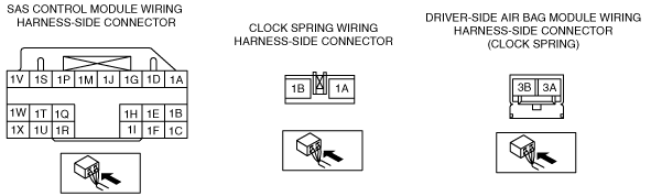
• Inspect for continuity between clock spring connector terminals 1A—3A and 1B—3B.
-
Note
-
• Inspect the clock spring wiring harness for continuity while shaking it.
• Is there continuity?
|
Yes
|
Go to the next step.
|
|
No
|
Replace the clock spring.
|
|
3
|
INSPECT WIRING HARNESS BETWEEN CLOCK SPRING AND SAS CONTROL MODULE
• Remove the glove compartment.
• Disconnect the passenger‐side air bag module connector. (Vehicles with passenger-side air bag)
• Disconnect the driver and passenger‐side seat connectors. (Vehicles with side air bag)
• Disconnect the driver and passenger-side pre-tensioner seat belt connectors. (Vehicle with pre-tensioner seat belt)
• Remove the console.
• Disconnect the all SAS control module connectors.
• Inspect the wiring harness between SAS control module connector terminal 1S and clock spring connector terminal 1A, SAS control module connector terminal 1V and clock spring connector terminal 1B for the following:
-
― Short circuit between terminals
― Short to ground
― Open circuit
-
Note
-
• Inspect for continuity while shaking the wiring harness between the SAS control module and clock spring.
• Is the wiring harness normal?
|
Yes
|
Go to the next step.
|
|
No
|
Replace the wiring harness between the SAS control module and clock spring.
|
|
4
|
INSPECT THE WIRING HARNESS BETWEEN THE SAS CONTROL MODULE AND DRIVER-SIDE AIR BAG MODULE FOR A SHORT CIRCUIT TO THE POWER SUPPLY
• Connect the negative battery cable.
• Turn the ignition (F2, G6)/engine (WLT-1, WLT-2, WL-C, WE-C) switch to ON position with SAS control module connector and clock spring connector disconnected.
• Measure the voltage of SAS control module connector terminals 1S and 1V.
-
Note
-
• Measure the voltage while shaking the wiring harness between the SAS control module and driver-side air bag module.
• Is the voltage measured?
|
Yes
|
Replace the wiring harness between the SAS control module and clock spring.
|
|
No
|
Go to the next step.
|
|
5
|
INSPECT DRIVER-SIDE AIR BAG MODULE
• Connect the leads of the SST (Fuel and thermometer checker) or apply 2 ohms resistance to clock spring connector terminals 3A and 3B.
• Set the resistance of the SST (Fuel and thermometer checker) to the 2 ohms position.
• Except for the driver-side air bag module connector, reconnect all disconnected connectors.
• Connect the negative battery cable.
• Turn the ignition (F2, G6)/engine (WLT-1, WLT-2, WL-C, WE-C) switch to ON position.
• Clear the DTC for the SAS control module using the M-MDS.
• Perform the DTC inspection for the SAS control module using the M-MDS.
• Are the same DTCs present?
|
Yes
|
Go to the next step.
|
|
No
|
Replace the driver-side air bag module.
|
|
6
|
PERFORM SAS CONTROL MODULE DTC INSPECTION
• Turn the ignition (F2, G6)/engine (WLT-1, WLT-2, WL-C, WE-C) switch to LOCK position.
• Disconnect the negative battery cable and wait for 1min or more.
• Disconnect the SST (Fuel and thermometer checker) or the 2 ohms resistance.
• Connect the driver-side air bag module connector.
• Connect the negative battery cable.
• Turn the ignition (F2, G6)/engine (WLT-1, WLT-2, WL-C, WE-C) switch to ON position.
• Clear the DTC for the SAS control module using the M-MDS.
• Perform the DTC inspection for the SAS control module using the M-MDS.
• Are the same DTCs present?
|
Yes
|
Replace the SAS control module.
|
|
No
|
DTC troubleshooting completed.
|