 |
absggn00000359
INPUT/OUTPUT CHECK MODE OPERATION
id092200100900
Operation procedure
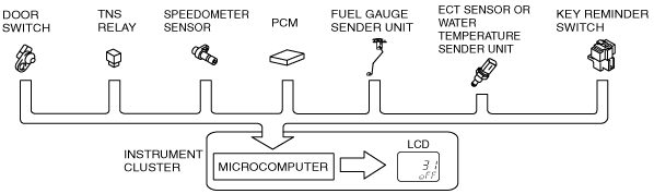
Input circuit check
|
Check code |
Parts sending input signal |
|---|---|
|
04
|
Door switch
|
|
08
|
TNS relay
|
|
09
|
Headlight switch
|
|
10
|
Vehicle speed signal
|
|
11
|
Engine speed signal
|
|
22
|
Fuel gauge sender unit
|
|
24
|
• ECT sensor
• Water temperature sender unit
|
|
29
|
Rear fog light switch
|
|
31
|
Key reminder switch
|
|
40
|
Front fog light relay
|
absggn00000359
|
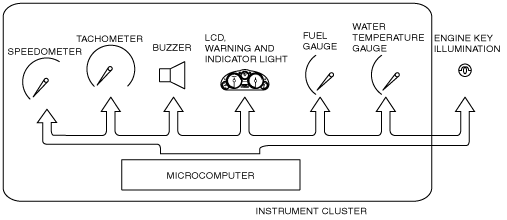
Individual circuit check
|
Check code |
Parts sending input signal |
|---|---|
|
12
|
Speedometer
|
|
13
|
Tachometer
|
|
14
|
Buzzer
|
|
15
|
Rear fog light relay
|
|
16
|
Fuel-level warning light
|
|
18
|
Engine key illumination output
|
|
23
|
Fuel gauge
|
|
25
|
Water temperature gauge
|
|
26
|
LCD, warning and indicator light
|
absggn00000360
|