 |
bwl1ge00000032
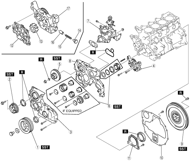
CYLINDER BLOCK DISASSEMBLY (II) [WLT-1, WLT-2, WL-3]
id011097500700
1. Disassemble in the order shown in the figure.
bwl1ge00000032
|
|
1
|
Crankshaft pulley
|
|
2
|
Fuel injection pump pulley
|
|
3
|
Timing gear cover
|
|
4
|
Oil pump
|
|
5
|
Fuel injection pump gear
|
|
6
|
Timing gear
|
|
7
|
Fuel injection pump
|
|
8
|
Timing gear case
|
|
9
|
Flywheel
(See Flywheel Disassembly Note.)
|
|
10
|
End plate
|
|
11
|
Rear cover
(See Rear Cover Disassembly Note.)
|
|
12
|
Oil pump cover
|
|
13
|
Driven gear
|
|
14
|
Plug
|
|
15
|
Plunger spring
|
|
16
|
Control plunger
|
|
17
|
Oil pump body
|
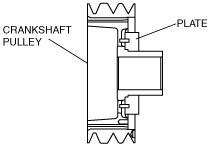
Crankshaft Pulley Disassembly Note
1. Remove the crankshaft pulley using the SST.
bwl1ge00000033
|
bwl1ge00000034
|
Fuel Injection Pump Pulley Disassembly Note
1. Remove the fuel injection pump pulley using the SST.
bwl1ge00000035
|
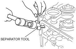
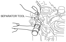
Timing Gear Cover Disassembly Note
1. Remove the timing gear cover using a separator tool.
bwl1ge00000036
|
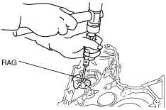
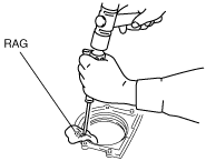
2. Remove the oil seal using a screwdriver protected with a rag.
bwl1ge00000037
|
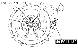
Fuel Injection Pump Gear Disassembly Note
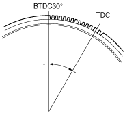
1. Set the No.1 cylinder to TDC of compression.
2. Rotate the flywheel ring gear from TDC to approximately 30° BTDC (about 13 teeth on the gear).
bwl1ge00000038
|
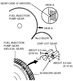
3. Verify that the end-gap (V groove) of the timing gear case and the chip cut gear of the fuel injection pump gear are aligned.
bwl1ge00000039
|
4. Fix the scissors gear to the fuel injection pump gear using a lock bolt (M8×1.25; length under the bolt head is approximately 14 mm {0.55 in}).
bwl1ge00000040
|
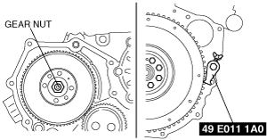
5. Hold the crankshaft using the SST and loosen the gear nut.
bwl1ge00000041
|
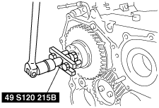
6. Remove the fuel injection pump gear using the SST.
bwl1ge00000042
|
Timing Gear Case Disassembly Note
1. Remove the timing gear case using the separator tool.
bwl1ge00000043
|
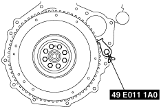
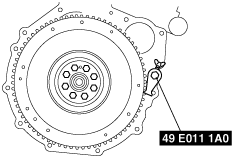
Flywheel Disassembly Note
1. Remove the flywheel using the SST.
bwl1ge00000044
|
Rear Cover Disassembly Note
1. Remove the oil seal using a screwdriver protected with a rag.
bwl1ge00000045
|