CONNECTING ROD OIL CLEARANCE INSPECTION/REPAIR [WLT-1, WLT-2, WL-3]
id011097502900
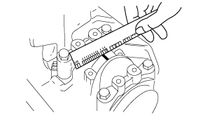
1. Position a plastigage on top of the journals in the axial direction.
2. Install the connecting rod cap. (See CYLINDER BLOCK ASSEMBLY (I) [WLT-1, WLT-2, WL-3].)
3. Remove the connecting rod cap.
4. Measure the crankpin oil clearance.
-
• If the clearance exceeds the maximum, replace the connecting rod bearing or grind the crankpin and use undersized bearings so that the specified clearance is obtained.
-
Standard connecting rod oil clearance
-
0.025—0.052 mm {0.0010—0.0020 in}
-
Maximum connecting rod oil clearance
-
0.08 mm {0.0031 in}
-
Connecting rod bearing thickness
-
Standard: 1.507—1.516 mm {0.0594—0.0596 in}
0.25 {0.01} undersize: 1.624—1.634 mm {0.0640—0.0643 in}
0.50 {0.02} undersize: 1.749—1.759 mm {0.0689—0.0692 in}
0.75 {0.03} undersize: 1.874—1.884 mm {0.0738—0.0741 in}