 |
bwl1ge00000099
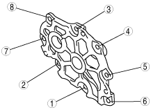
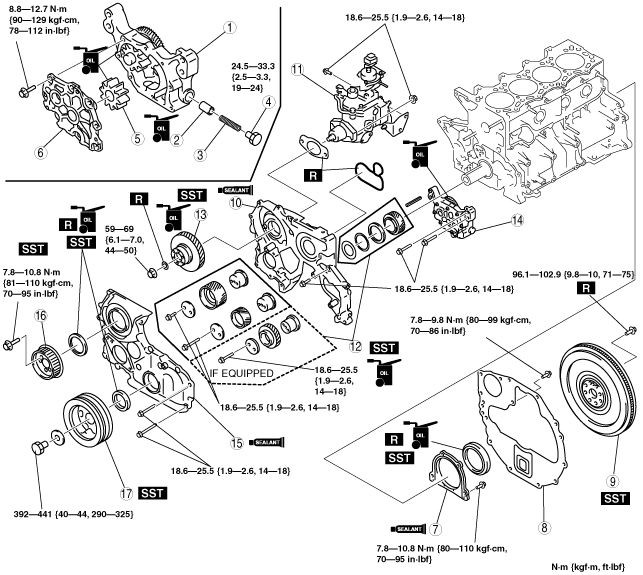
CYLINDER BLOCK ASSEMBLY (II) [WLT-1, WLT-2, WL-3]
id011097504100
1. Assemble in the order indicated in the table.
bwl1ge00000099
|
|
1
|
Oil pump body
|
|
2
|
Control plunger
|
|
3
|
Plunger spring
|
|
4
|
Plug
|
|
5
|
Driven gear
|
|
6
|
Oil pump cover
(See Oil Pump Cover Assembly Note.)
|
|
7
|
Rear cover, end plate
|
|
8
|
End plate
|
|
9
|
Flywheel
(See Flywheel Assembly Note.)
|
|
10
|
Timing gear case
|
|
11
|
Fuel injection pump
|
|
12
|
Timing gear
|
|
13
|
Fuel injection pump gear
|
|
14
|
Oil pump
|
|
15
|
Timing gear cover
|
|
16
|
Fuel injection pump pulley
|
|
17
|
Crankshaft pulley
|
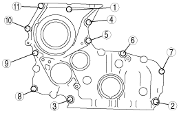
Oil Pump Cover Assembly Note
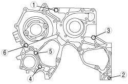
1. Tighten the bolts in two or three steps in the order shown in the figure.
bwl1ge00000100
|
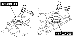
Rear Cover, End Plate Assembly Note
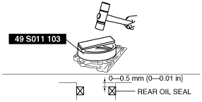
1. Apply soapy water along the perimeter of the new oil seal.
2. Push the oil seal slightly in by hand.
3. Tap the oil seal in evenly by using the SST and a hammer.
bwl1ge00000101
|
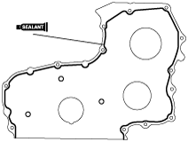
4. To ensure that the oil seal is installed correctly, measure the distance between the end of the rear cover and the face of the oil seal.
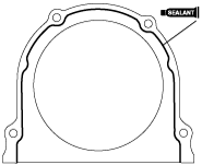
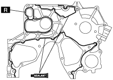
5. Apply silicone sealant to the rear cover as shown in the figure.
bwl1ge00000102
|
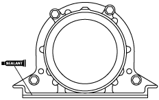
6. Apply silicone sealant to the rear cover as shown in the figure.
bwl1ge00000103
|
7. Install the end plate.
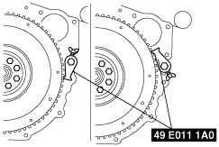
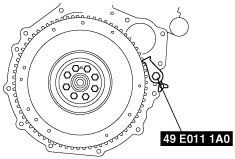
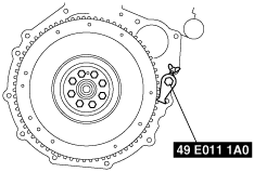
Flywheel Assembly Note
1. Hold the crankshaft using the SST.
2. Tighten the bolts in the order shown in the figure.
bwl1ge00000104
|
Timing Gear Case Assembly Note
1. Install the new O‐ring.
2. Apply silicone sealant to the timing gear case as shown in the figure. Do not apply sealant to the O-ring.
bwl1ge00000105
|
3. Tighten the bolts in two or three steps in the order shown in the figure.
bwl1ge00000106
|
Timing Gear, Fuel Injection Pump Gear Assembly Note
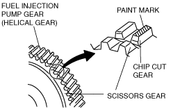
1. Put a paint mark on the chip cut gear of the fuel injection pump gear.
bwl1ge00000107
|
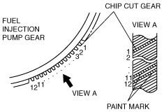
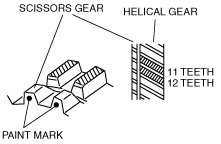
2. Put a paint mark on the 11th and 12th teeth of the helical gear counting clockwise from the chip cut gear.
bwl1ge00000108
|
3. Verify that the 11th and 12th teeth of fuel injection pump gear (helical gear) and the teeth of the scissors gear are aligned, then put a paint mark on the scissors gear.
bwl1ge00000109
|
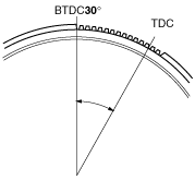
4. Set the No.1 cylinder to TDC of compression.
5. Rotate the flywheel ring gear from TDC to approximately 30° BTDC (13 teeth on the gear).
bwl1ge00000110
|
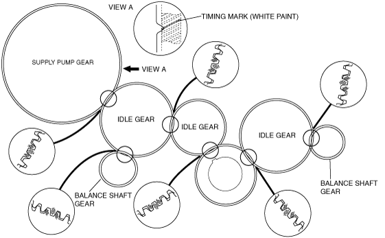
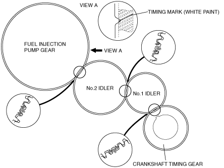
6. Align the timing marks. For the fuel injection pump gear, align the timing mark as shown in the figure (View A).
WLT-1, WLT-2
bwl1ge00000258
|
WL-3
bwl1ge00000111
|
7. Remove the lock bolt.
bwl1ge00000112
|
8. Tighten the bolts using the SST.
bwl1ge00000113
|
Timing Gear Cover Assembly Note
1. Apply soapy water along the perimeter of the new oil seal.
2. Push the oil seal slightly in by hand.
3. Tap the oil seal in evenly using the SST and a hammer.
bwl1ge00000114
|
4. To ensure that the oil seal is installed correctly, measure the distance between the end of the timing gear cover and the face of the oil seal.
5. Apply silicone sealant to the timing gear cover as shown in the figure.
bwl1ge00000115
|
6. Tighten the bolts in two or three steps in the order shown in the figure.
bwl1ge00000116
|
Fuel Injection Pump Pulley Assembly Note
1. Install the fuel injection pump pulley using the SST.
bwl1ge00000117
|
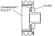
Crankshaft Pulley Assembly Note
bwl1ge00000118
|
1. Install the crankshaft pulley using the SST.
bwl1ge00000119
|