 |
bwl1ge00000213
CYLINDER BLOCK DISASSEMBLY (II) [WL-C, WE-C]
id0110b6500700
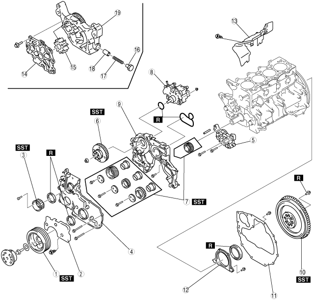
1. Disassemble in the order shown in the figure.
bwl1ge00000213
|
|
1
|
Crankshaft pulley
|
|
2
|
Seal plate
|
|
3
|
Supply pump pulley
|
|
4
|
Timing gear cover
|
|
5
|
Oil pump
|
|
6
|
Supply pump gear
|
|
7
|
Timing gear
|
|
8
|
Supply pump
|
|
9
|
Timing gear case
|
|
10
|
Dual-mass flywheel
|
|
11
|
End plate
|
|
12
|
Rear cover
(See Rear Cover Disassembly Note.)
|
|
13
|
Seal plate
|
|
14
|
Oil pump cover
|
|
15
|
Driven gear
|
|
16
|
Plug
|
|
17
|
Plunger spring
|
|
18
|
Control plunger
|
|
19
|
Oil pump body
|
Crankshaft Pulley Disassembly Note
1. Remove the crankshaft pulley using the SST.
bwl1ge00000214
|
Supply Pump Pulley Disassembly Note
1. Remove the supply pump pulley using the SST.
bwl1ge00000215
|
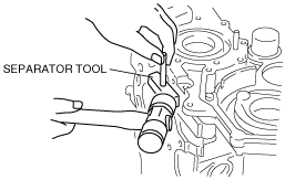
Timing Gear Cover Disassembly Note
1. Remove the timing gear cover using a separator tool.
bwl1ge00000216
|
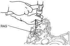
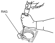
2. Remove the oil seal using a screwdriver protected with a rag,
bwl1ge00000217
|
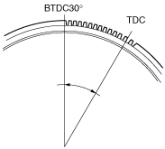
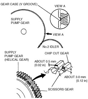
Supply Pump Gear Disassembly Note
1. Set the No.1 cylinder to TDC of compression.
2. Rotate the flywheel ring gear from TDC to approximately 30° BTDC (about 13 teeth on the gear).
bwl1ge00000218
|
3. Verify that the end-gap (V groove) of the timing gear case and the chip cut gear of the fuel injection pump gear are aligned.
bwl1ge00000219
|
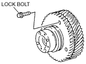
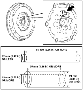
4. Fix the scissors gear to the supply pump gear using a lock bolt (M6×1.0; length under the bolt head is approximately 16 mm {0.63 in}).
bwl1ge00000220
|
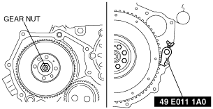
5. Hold the crankshaft using the SST and loosen the gear nut.
bwl1ge00000221
|
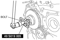
6. Remove the supply pump gear using the SST and bolt (M6X1.0, Length 30mm {1.18 in}).
bwl1ge00000222
|
Timing Gear Case Disassembly Note
1. Remove the timing gear case using the separator tool.
bwl1ge00000223
|
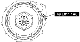
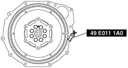
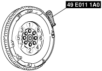
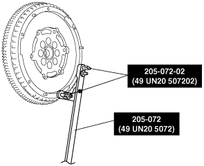
Dual-mass flywheel Disassembly Note
1. Lock the dual-mass flywheel against rotation using the SST (49 E011 1A0).
2. Loosen the lock bolts uniformly and gradually in the order shown in the figure, and remove them.
bwl1ge00000224
|
bwl1ge00000225
|
bwl1ge00000226
|
3. Remove the dual-mass flywheel.
4. Remove the SST.
Rear Cover Disassembly Note
1. Remove the oil seal using a screwdriver protected with a rag.
bwl1ge00000227
|