 |
bwl1ge00000266
CYLINDER BLOCK ASSEMBLY (I) [WL-C, WE-C]
id0110b6504000
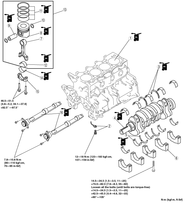
1. Assemble in the order indicated in the table.
bwl1ge00000266
|
|
1
|
Cylinder block
|
|
2
|
Oil jet valve, nozzle
|
|
3
|
Upper main bearing, upper thrust bearing
|
|
4
|
Crankshaft
|
|
5
|
Lower main bearing, lower thrust bearing
|
|
6
|
Main bearing cap
|
|
7
|
Connecting rod
|
|
8
|
Piston
|
|
9
|
Piston pin
|
|
10
|
Piston pin clip
|
|
11
|
Piston ring
(See Piston Ring Assembly Note.)
|
|
12
|
Upper connecting rod bearing
|
|
13
|
Piston, connecting rod
|
|
14
|
Lower connecting rod bearing
|
|
15
|
Connecting rod cap
|
|
16
|
Balance shaft
|
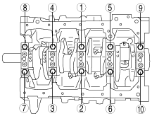
Main Bearing Cap Assembly Note
1. Apply clean engine oil to the bolt threads and seat faces of the lower cylinder block bolts.
2. Tighten the bolts in two or three steps in the order shown in the figure.
bwl1ge00000267
|
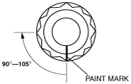
3. Put a paint mark on each bolt head.
4. Using the marks as a reference, tighten the bolts by turning each 90°—105° as in Step 2.
bwl1ge00000268
|
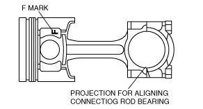
Piston, Connecting Rod, Piston Pin Assembly Note
1. Install one piston pin clip.
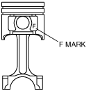
2. Assemble the piston and connecting rod in the direction indicated in the figure.
3. Apply clean engine oil to the piston pin.
4. Install the piston pin until the pin contacts the clip as shown. If the pin cannot be installed easily, heat the piston.
bwl1ge00000269
|
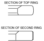
Piston Ring Assembly Note
1. Install the oil ring.
2. Install the second ring with R mark side upward.
3. Install the top ring with tapered face side upward.
bwl1ge00000270
|
Piston, Connecting Rod Assembly Note
1. Insert the piston and connecting rod assembly into the cylinder with the F mark facing the front of the engine.
bwl1ge00000271
|
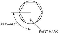
2. Tighten the connecting rod cap bolts in two or three steps.
3. Put a paint mark on each bolt.
4. Using the marks as a reference, tighten the bolts by turning each 82.5°—97.5°
bwl1ge00000272
|