 |
bwl1ge00000307
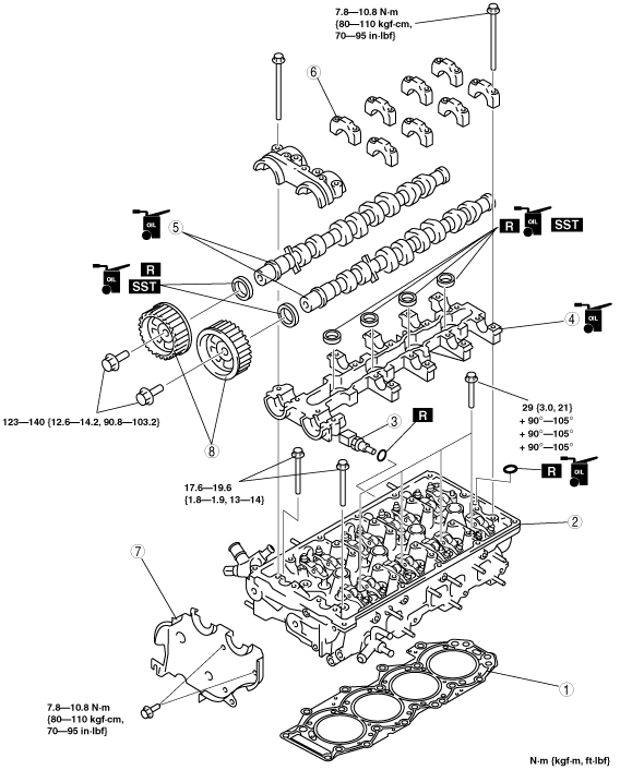
CYLINDER HEAD ASSEMBLY (II) [WL-C, WE-C]
id0110b6504400
1. Assemble in the order indicated in the table.
bwl1ge00000307
|
|
1
|
Cylinder head gasket
|
|
2
|
Cylinder head
(See Cylinder Head Assembly Note.)
|
|
3
|
ECT sensor
|
|
4
|
Camshaft cap lower
|
|
5
|
Camshaft
|
|
6
|
Camshaft cap upper
|
|
7
|
Seal plate
(See Seal Plate Assembly Note.)
|
|
8
|
Camshaft pulley
|
Cylinder Head Gasket Assembly Note
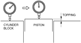
1. Measure the piston topping of all the cylinders.
bwl1ge00000162
|
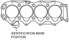
2. Choose the gasket according to each measured piston topping.
bwl1ge00000163
|
Cylinder head gasket select table
|
Piston topping (mm {in}) |
Cylinder head gasket identification mark |
|---|---|
|
0.080—0.190 {0.004—0.007}
|
 |
|
0.135—0.255 {0.006—0.010}
|
 |
|
0.200—0.310 {0.008—0.012}
|
 |
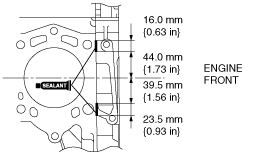
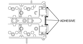
3. Apply silicone sealant to the cylinder block as shown in the figure.
bwl1ge00000167
|
Cylinder Head Assembly Note
1. Before installing the cylinder head bolts, inspect their length. (See BOLT INSPECTION [WL-C, WE-C].)
2. Apply clean engine oil to the threads and the seat face of each bolt and install them.
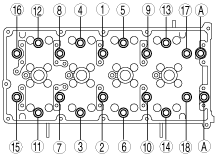
3. Tighten the bolts in two or three steps in the order shown in the figure.
bwl1ge00000168
|
4. Retighten the bolts in the order shown in the figure until all the bolts are tightened to 29 N·m {3.0 kgf·m, 2.1 ft·lbf}.
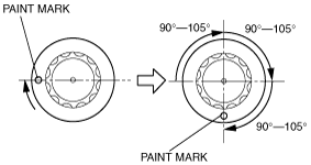
5. Put a paint mark on each bolt head.
bwl1ge00000169
|
6. Using the marks as a reference, tighten the bolts by turning each 90°—105°in the sequence shown.
7. Further tighten each bolt by turning another 90°—105°.
8. Further tighten each bolt by turning another 90°—105°.
9. Apply adhesive to the thread of bolt A.
10. Tighten bolts A.
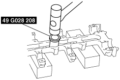
Camshaft Cap Lower Assembly Note
1. Apply engine oil along the perimeter of the new oil seal.
2. Push the oil seal slightly in by hand.
3. Tap the oil seal in evenly using the SST and a hammer.
absggw00000530
|
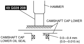
4. To ensure that the oil seal is installed correctly, measure the distance between the end of the camshaft cap lower and the face of the camshaft cap lower oil seal.
absggw00000616
|
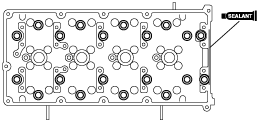
5. Apply silicone sealant to the cylinder head as shown in the figure.
bwl1ge00000171
|
Camshaft Cap Upper Assembly Note
1. Apply adhesive to the front camshaft cap mounting surfaces as shown in the figure.
bwl1ge00000172
|
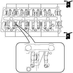
2. Apply the gear oil (SAE No. 90 or equivalent) to each journal of the camshaft cap lower as shown in the figure.
bwl1ge00000308
|
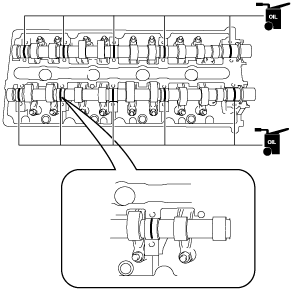
3. Apply the gear oil (SAE No. 90 or equivalent) to each journal of the camshaft as shown in the figure.
bwl1ge00000310
|
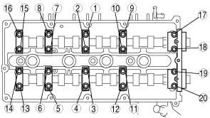
4. Tighten the camshaft cap bolts gradually in three or four steps in the order shown in the figure.
bwl1ge00000173
|
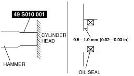
5. Apply soapy water along the perimeter of the new oil seal.
6. Push the oil seal slightly in by hand.
7. Tap the oil seal lightly into the cylinder head using the SST and a hammer.
bwl1ge00000174
|
8. To ensure that the oil seal is installed correctly, measure the distance between the end of the cylinder head and the face of the oil seal.
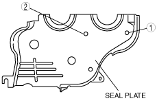
Seal Plate Assembly Note
1. Tighten the seal plate bolts in the order indicated in the figure.
bwl1ge00000175
|
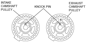
Camshaft Pulley Assembly Note
1. Install the camshaft pulleys, positioning the knock pins as shown in the figure.
bwl1ge00000176
|
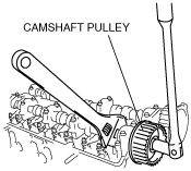
2. Hold the camshaft using a wrench on the cast hexagon.
bwl1ge00000177
|