 |
bms1zm00000029
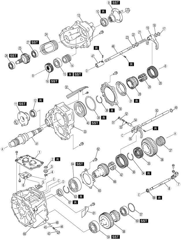
TRANSFER DISASSEMBLY
id031600500200
Before Service Precautions
Transfer Disassembly
1. Disassemble in the order shown in the figure.
bms1zm00000029
|
|
1
|
Control case
|
|
2
|
E-ring
|
|
3
|
Spacer
|
|
4
|
Reverse gate spring
|
|
5
|
Reverse gate lever
|
|
6
|
Guide plate
|
|
7
|
Control rod end
|
|
8
|
Control rod
|
|
9
|
Companion flange (rear case side)
|
|
10
|
Oil seal (rear case)
|
|
11
|
Companion flange (center case side)
|
|
12
|
Oil seal (center case)
|
|
13
|
Rear case
|
|
14
|
Speed drive gear
|
|
15
|
Mainshaft rear bearing
|
|
16
|
2W/4W clutch hub
|
|
17
|
Snap ring
|
|
18
|
Spacer
|
|
19
|
2W/4W shift fork
|
|
20
|
2W/4W hub sleeve
|
|
21
|
Spring
|
|
22
|
Collar
|
|
23
|
Snap ring
|
|
24
|
Chain
|
|
25
|
Front drive shaft
|
|
26
|
Front drive shaft bearing (center case side)
|
|
27
|
Front drive shaft bearing (rear case side)
|
|
28
|
Sprocket
|
|
29
|
Needle bearing
|
|
30
|
Center bearing retainer
|
|
31
|
Oil catcher
|
|
32
|
Oil passage
|
|
33
|
Center case
|
|
34
|
Retaining ring
|
|
35
|
H/L clutch hub
|
|
36
|
Low gear
|
|
37
|
Needle bearing
|
|
38
|
Retaining ring
|
|
39
|
Retaining ring
|
|
40
|
Mainshaft center bearing
|
|
41
|
Mainshaft
|
|
42
|
Needle bearing
|
|
43
|
Retaining bolt
|
|
44
|
Spring
|
|
45
|
Steel ball
|
|
46
|
2W/4W shift rod
|
|
47
|
2W/4W shift end
|
|
48
|
Interlock pin
|
|
49
|
Snap ring
|
|
50
|
H/L shift rod
|
|
51
|
Snap ring
|
|
52
|
Plain washer
|
|
53
|
Spring
|
|
54
|
Plunger
|
|
55
|
H/L shift fork
|
|
56
|
H/L hub sleeve
|
|
57
|
Adjustment shim
|
|
58
|
Countershaft
|
|
59
|
Countershaft front bearing (front case side)
|
|
60
|
Countershaft rear bearing (center case side)
|
|
61
|
Baffle plate
|
|
62
|
Retaining bolt
|
|
63
|
Retaining ring
|
|
64
|
Maindrive gear bearing
|
|
65
|
Retainer
|
|
66
|
Maindrive gear
|
|
67
|
Oil seal (control rod)
|
|
68
|
Oil seal (front case)
|
|
69
|
Front case
|
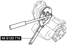
Companion Flange Disassembly Note
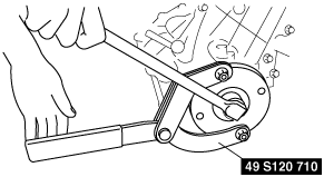
1. Hold the companion flange using the SST.
Center case side
bms1zm00000030
|
Rear case side
bms1zm00000031
|
2. Remove the locknut.
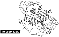
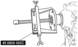
3. Remove the companion flange using the SST.
Center case side
bms1zm00000032
|
Rear case side
bms1zm00000033
|
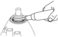
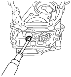
Oil Seal (Rear Case) Disassembly Note
1. Remove the oil seal (rear case) using a flathead screwdriver as shown in the figure.
bms1zm00000034
|
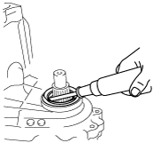
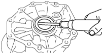
Oil Seal (Center Case) Disassembly Note
1. Remove the oil seal (center case) using a flathead screwdriver as shown in the figure.
bms1zm00000035
|
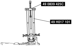
Mainshaft Rear Bearing Disassembly Note
1. Remove the mainshaft rear bearing using the SSTs.
bms1zm00000036
|
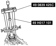
2W/4W Clutch Hub Disassembly Note
1. Remove the 2W/4W clutch hub using the SSTs.
bms1zm00000037
|
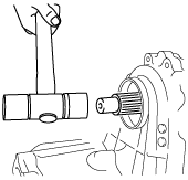
Chain, Front Drive Shaft and Sprocket Disassembly Note
1. Remove the front drive shaft using the plastic hammer.
bms1zm00000038
|
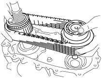
2. Remove the chain, front drive shaft and sprocket as a single unit.
bms1zm00000039
|
Front Drive Shaft Bearing Disassembly Note
1. Remove the front drive shaft bearing using the SSTs and press.
Center case side
bms1zm00000040
|
Rear case side
bms1zm00000041
|
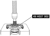
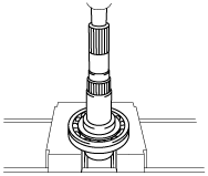
Mainshaft Center Bearing Disassembly Note
1. Remove the mainshaft front bearing using the press.
bms1zm00000042
|
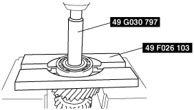
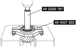
Countershaft Bearing Disassembly Note
1. Remove the countershaft bearing using the SSTs and press.
Front case side
bms1zm00000043
|
Center case side
bms1zm00000044
|
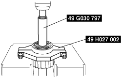
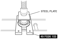
Maindrive Gear Bearing Disassembly Note
1. Remove the maindrive gear bearing using the SST, press and steel plate.
bms1zm00000045
|
Oil Seal (Control Rod) Disassembly Note
1. Remove the oil seal (control rod) using a flathead screwdriver as shown in the figure.
bms1zm00000046
|
Oil Seal (Front Case) Disassembly Note
1. Remove the oil seal (front case) using a flathead screwdriver as shown in the figure.
bms1zm00000047
|