 |
bms1zm00000233
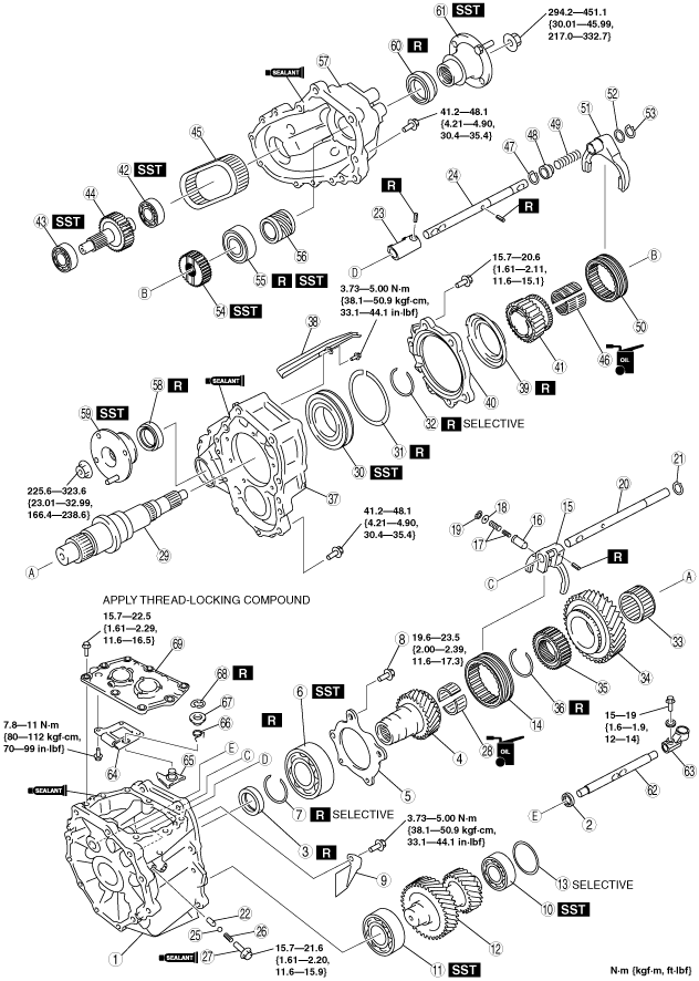
TRANSFER ASSEMBLY
id031600500300
Before Service Precautions
Transfer Assembly
bms1zm00000233
|
|
1
|
Front case
|
|
2
|
Oil seal (control rod)
|
|
3
|
Oil seal (front case)
|
|
4
|
Maindrive gear
|
|
5
|
Retainer
|
|
6
|
Maindrive gear bearing
|
|
7
|
Retaining ring
|
|
8
|
Retaining bolt
|
|
9
|
Baffle plate
|
|
10
|
Countershaft rear bearing (center case side)
|
|
11
|
Countershaft front bearing (front case side)
|
|
12
|
Countershaft
(See Countershaft Assembly Note.)
|
|
13
|
Adjustment shim
(See Countershaft Assembly Note.)
|
|
14
|
H/L hub sleeve
|
|
15
|
H/L shift fork
|
|
16
|
Plunger
|
|
17
|
Spring
|
|
18
|
Plain washer
|
|
19
|
Snap ring
|
|
20
|
H/L shift rod
|
|
21
|
Snap ring
|
|
22
|
Interlock pin
|
|
23
|
2W/4W shift end
|
|
24
|
2W/4W shift rod
|
|
25
|
Steel ball
|
|
26
|
Spring
|
|
27
|
Retaining bolt
|
|
28
|
Needle bearing
|
|
29
|
Mainshaft
|
|
30
|
Mainshaft center bearing
|
|
31
|
Retaining ring
|
|
32
|
Retaining ring
|
|
33
|
Needle bearing
|
|
34
|
Low gear
|
|
35
|
H/L clutch hub
|
|
36
|
Retaining ring
|
|
37
|
Center case
(See Center Case Assembly Note.)
|
|
38
|
Oil passage
(See Oil Passage Assembly Note.)
|
|
39
|
Oil catcher
(See Oil Catcher Assembly Note.)
|
|
40
|
Center bearing retainer
|
|
41
|
Sprocket
|
|
42
|
Front drive shaft bearing (rear case side)
|
|
43
|
Front drive shaft bearing (center case side)
|
|
44
|
Front drive shaft
|
|
45
|
Chain
|
|
46
|
Needle bearing
|
|
47
|
Snap ring
|
|
48
|
Collar
|
|
49
|
Spring
|
|
50
|
2W/4W hub sleeve
|
|
51
|
2W/4W shift fork
|
|
52
|
Spacer
|
|
53
|
Snap ring
|
|
54
|
2W/4W clutch hub
|
|
55
|
Mainshaft rear bearing
|
|
56
|
Speed drive gear
|
|
57
|
Rear case
(See Rear Case Assembly Note.)
|
|
58
|
Oil seal (center case)
|
|
59
|
Companion flange (center case side)
|
|
60
|
Oil seal (rear case)
|
|
61
|
Companion flange (rear case side)
|
|
62
|
Control rod
|
|
63
|
Control rod end
|
|
64
|
Guide plate
|
|
65
|
Reverse gate lever
|
|
66
|
Reverse gate spring
|
|
67
|
Spacer
|
|
68
|
E-ring
|
|
69
|
Control case
(See Control Case Assembly Note.)
|
Oil Seal (control rod) Assembly Note
1. Apply specified grease to the lip of a new oil seal.
2. Install the oil seal (control rod) using the SST.
bms1zm00000049
|
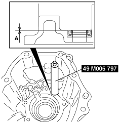
Oil Seal (front case) Assembly Note
1. Apply specified grease to the lip of a new oil seal.
2. Install the oil seal (front case) using the SST.
bms1zm00000050
|
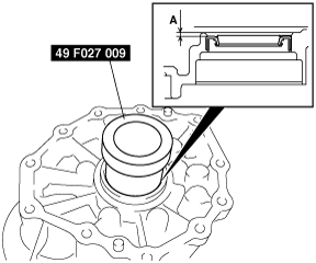
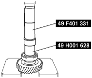
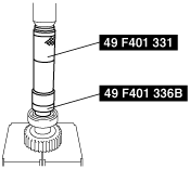
Maindrive Gear Bearing Assembly Note
1. Assemble the maindrive gear bearing using the SST and press.
bms1zm00000051
|
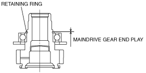
2. Install the retaining ring.
3. Measure the clearance between the retaining ring and groove of the maindrive gear.
bms1zm00000052
|
Maindrive gear bearing retaining ring
|
Thickness (mm {in}) |
|---|
|
2.60 {0.102}
|
|
2.67 {0.105}
|
|
2.74 {0.108}
|
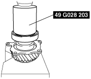
Countershaft Bearing Assembly Note
1. Assemble the countershaft bearing using the SSTs and press.
Front case side
bms1zm00000053
|
Center case side
bms1zm00000054
|
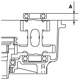
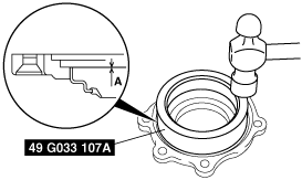
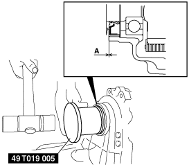
Countershaft Assembly Note
1. Assemble the countershaft to the front case.
2. Measure the depth A as shown in the figure.
bms1zm00000055
|
3. Select the correct countershaft adjustment shim thickness.
Countershaft adjustment shim selective chart
|
Dimension A (mm {in}) |
Shim thickness (mm {in}) |
|---|---|
|
25.0—25.1
{0.985—0.988}
|
0.5 {0.020}
|
|
25.1—25.2
{0.989—0.992}
|
0.4 {0.016}
|
|
25.2—25.3
{0.993—0.996}
|
0.3 {0.012}
|
|
25.3—25.4
{0.997—1.000}
|
0.2 {0.008}
|
|
25.4—25.5
{1.000—1.003}
|
0.1 {0.004}
|
|
25.5—25.6
{1.004—1.007}
|
-
|
4. Install the adjustment shim.
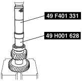
Mainshaft and Mainshaft Center Bearing Assembly Note
1. Assemble the mainshaft center bearing using the SST and press.
bms1zm00000056
|
2. Measure the clearance between the retaining ring and groove of the mainshaft.
bms1zm00000057
|
Mainshaft center bearing retaining ring
|
Thickness (mm {in}) |
|---|
|
3.1 {0.122}
|
|
3.2 {0.126}
|
|
3.3 {0.130}
|
3. Assemble the mainshaft to the center case using the plastic hammer.
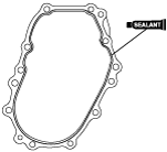
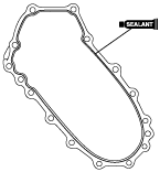
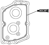
Center Case Assembly Note
1. Apply sealant to the contact surfaces of the front case and center case as shown in the figure.
bms1zm00000058
|
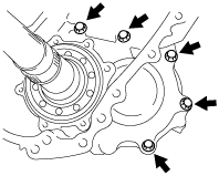
2. Assemble the center case.
bms1zm00000059
|
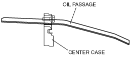
Oil Passage Assembly Note
1. Assemble the oil passage to the center case.
bms1zm00000060
|
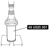
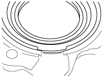
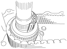
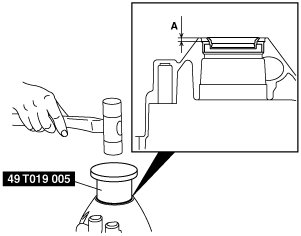
Oil Catcher Assembly Note
1. Align the oil catcher groove as shown in the figure.
bms1zm00000061
|
2. Apply specified grease to the lip of a new oil seal.
3. Install the oil catcher using the SST.
bms1zm00000062
|
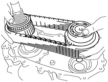
Chain, Front Drive Shaft and Sprocket Assembly Note
1. Assemble the chain, front drive shaft and sprocket as a single unit.
bms1zm00000063
|
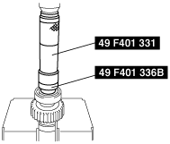
2. Install the needle bearings while turning the mainshaft.
bms1zm00000064
|
Front Drive Shaft Bearing Assembly Note
1. Assemble the front drive shaft bearing using the SSTs and press.
Center case side
bms1zm00000065
|
Rear case side
bms1zm00000066
|
2W/4W Clutch Hub Assembly Note
1. Assemble the 2W/4W clutch hub using the SST.
bms1zm00000067
|
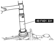
Mainshaft Rear Bearing Assembly Note
1. Assemble the mainshaft rear bearing using the SST.
bms1zm00000068
|
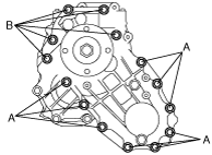
Rear Case Assembly Note
1. Apply sealant to the contact surfaces of the center case and rear case as shown in the figure.
bms1zm00000069
|
2. Assemble the rear case.
bms1zm00000070
|
Oil Seal (center case) Assembly Note
1. Apply specified grease to the lip of a new oil seal.
2. Install the oil seal (center case) using the SST.
bms1zm00000071
|
Oil Seal (rear case) Assembly Note
1. Apply specified grease to the lip of a new oil seal.
2. Install the oil seal (rear case) using the SST.
bms1zm00000072
|
Control Case Assembly Note
1. Apply sealant to the contact surfaces of the control case and transfer case as shown in the figure.
bms1zm00000073
|
2. Install the control case to the transfer case.