 |
bms1zm00000174
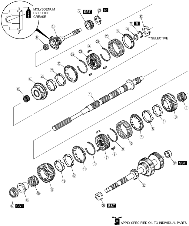
1ST/2ND GEAR COMPONENT, 3RD/4TH GEAR COMPONENT AND COUNTERSHAFT ASSEMBLY
id051100501800
1. Assemble in the order indicated in the table.
bms1zm00000174
|
|
1
|
Mainshaft
|
|
2
|
Needle bearing
|
|
3
|
2nd gear
|
|
4
|
Inner cone
|
|
5
|
Double cone
|
|
6
|
Synchronizer ring
|
|
7
|
1st/2nd clutch hub
|
|
8
|
Synchronizer key
|
|
9
|
Synchronizer key spring
|
|
10
|
Clutch hub sleeve
|
|
11
|
Synchronizer ring
|
|
12
|
Double cone
|
|
13
|
Inner cone
|
|
14
|
1st gear
|
|
15
|
Needle bearing
|
|
16
|
1st gear bearing inner race
|
|
17
|
Mainshaft center bearing
|
|
18
|
Needle bearing
|
|
19
|
3rd gear
|
|
20
|
Inner cone
|
|
21
|
Double cone
|
|
22
|
Synchronizer ring
|
|
23
|
Clutch hub
|
|
24
|
Synchronizer key
|
|
25
|
Synchronizer key spring
|
|
26
|
Clutch hub sleeve
|
|
27
|
Synchronizer ring
|
|
28
|
Spacer
|
|
29
|
Retaining ring
|
|
30
|
Needle bearing
|
|
31
|
Maindrive gear
|
|
32
|
Maindrive gear shaft bearing
|
|
33
|
Scoop ring
|
|
34
|
Needle bearing
|
|
35
|
Countershaft
|
|
36
|
Countershaft center bearing race
|
|
37
|
Countershaft front bearing race
|
2nd Gear, 1st Gear, Countershaft Assembly Note
1. If a type A 2nd gear, 1st gear, or countershaft is newly replaced, replace all of the other parts with new ones (type B). In addition, before assembly, verify that all parts are type B based on the number of teeth.
|
Item |
Type A (Number of teeth) |
Type B (Number of teeth) |
|
|---|---|---|---|
|
1st gear
|
38
|
39
|
|
|
2nd gear
|
35
|
36
|
|
|
Countershaft
|
Counter 1st gear
|
15
|
14
|
|
Counter 2nd gear
|
24
|
23
|
|
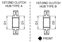
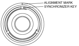
1st/2nd Clutch Hub Component Assembly Note
bms1zm00000242
|
bms1zm00000243
|
bms1zm00000175
|
|
|
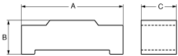
A |
B |
C |
|---|---|---|---|
|
1st/2nd
|
17.0 {0.669}
|
5.9 {0.23}
|
5.0 {0.20}
|
bms1zm00000176
|
bms1zm00000177
|
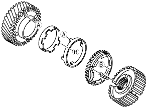
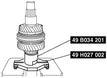
1. Using a SSTs and press, assemble the needle bearing, 2nd gear, synchronizer ring component (2nd), 1st/2nd clutch hub component, synchronizer ring component (1st), 1st gear, needle bearing, needle bearing race and mainshaft center bearing to the mainshaft at the same time.
bms1zm00000178
|
3rd/4th Clutch Hub Component Assembly Note
1. Assemble the 3rd/4th clutch hub component.
bms1zm00000175
|
|
|
A |
B |
C |
|---|---|---|---|
|
3rd/4th
|
17.0 {0.669}
|
5.9 {0.23}
|
5.0 {0.20}
|
bms1zm00000176
|
bms1zm00000177
|
2. Install the 3rd/4th clutch hub component to the mainshaft.
3. Install the spacer.
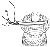
4. Install the retaining ring.
5. Measure the clearance between retaining ring and spacer.
bms1zm00000179
|
3rd/4th clutch hub retaining ring
|
Thickness (mm {in}) |
|---|
|
1.50 {0.0591}
|
|
1.55 {0.0610}
|
|
1.60 {0.0630}
|
|
1.65 {0.0650}
|
|
1.70 {0.0669}
|
|
1.75 {0.0689}
|
|
1.80 {0.0709}
|
|
1.85 {0.0728}
|
|
1.90 {0.0748}
|
|
1.95 {0.0768}
|
Maindrive Gear Shaft Bearing Assembly Note
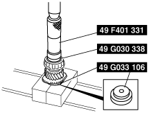
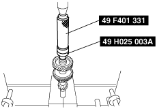
1. Assemble the maindrive gear shaft bearing using the SSTs.
bms1zm00000180
|
Countershaft Center Bearing Race Assembly Note
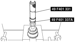
1. Assemble the countershaft center bearing race using the SSTs.
bms1zm00000181
|
Countershaft Front Bearing Race Assembly Note
1. Assemble the countershaft front bearing race using the SSTs.
bms1zm00000182
|