 |
bms1zm00000236
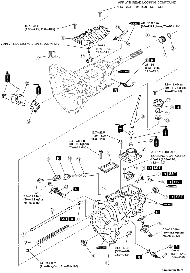
TOP COVER COMPONENT AND EXTENSION HOUSING ASSEMBLY
id051100502100
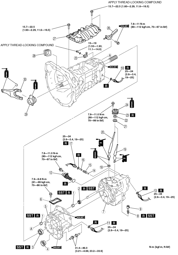
1. Assemble in the order indicated in the table.
4x2
bms1zm00000236
|
|
1
|
Steel ball
|
|
2
|
Speed drive gear
|
|
3
|
Retaining ring
|
|
4
|
Bush
(See Bush Assembly Note.)
|
|
5
|
Oil seal (control rod)
|
|
6
|
Sealing cap
(See Sealing Cap Assembly Note.)
|
|
7
|
Control rod
|
|
8
|
Oil passage
|
|
9
|
Funnel
|
|
10
|
Extension housing
|
|
11
|
Control rod end
|
|
12
|
Select spindle component
|
|
13
|
Select lock spindle
|
|
14
|
Select lock spindle spring
|
|
15
|
Spring cap
|
|
16
|
Oil seal (extension housing)
|
|
17
|
Control lever
|
|
18
|
Oil passage
|
|
19
|
Top cover, shift component
(See Top Cover Assembly Note.)
|
|
20
|
Blind cover
(See Blind Cover Assembly Note.)
|
|
21
|
Control case
|
|
22
|
Change seat
|
|
23
|
Shift lever
|
|
24
|
Change bush
|
|
25
|
Wave washer
|
|
26
|
Gasket
|
|
27
|
Dust boot
|
|
28
|
Neutral switch
|
|
29
|
Vehicle speed sensor
|
|
30
|
Back-up light switch
|
|
31
|
Dust boot
|
|
32
|
Release fork
|
|
33
|
Release collar
|
4x4
bms1zm00000237
|
|
1
|
Bush
(See Bush Assembly Note.)
|
|
2
|
Oil seal (control rod)
|
|
3
|
Oil seal (extension housing)
|
|
4
|
Funnel
|
|
5
|
Extension housing
|
|
6
|
Blind cover
(See Blind Cover Assembly Note.)
|
|
7
|
Transfer
|
|
8
|
Breather
(See Breather Assembly Note.)
|
|
9
|
Breather dust boot
|
|
10
|
Back-up light switch
|
|
11
|
Neutral switch
|
|
12
|
Vehicle speed sensor
|
|
13
|
4X4 indicator switch
|
|
14
|
Steel ball
|
|
15
|
Spring
|
|
16
|
Switch pin
|
|
17
|
Transfer neutral switch
|
|
18
|
Change seat
|
|
19
|
Transfer shift lever
|
|
20
|
Shift lever
|
|
21
|
Change bush
|
|
22
|
Wave washer
|
|
23
|
Gasket
|
|
24
|
Dust boot
|
|
25
|
Control rod end
|
|
26
|
Oil passage
|
|
27
|
Top cover, shift component
(See Top Cover Assembly Note.)
|
|
28
|
Dust boot
|
|
29
|
Release collar
|
|
30
|
Release fork
|
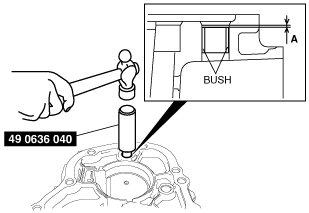
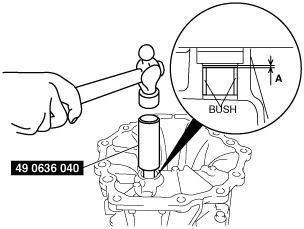
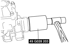
Bush Assembly Note
4x2
1. Install the bush using the SST.
bms1zm00000115
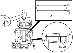
|
2. Install the bush using the suitable steel bar through the sealing cap hole as shown in the figure.
bms1zm00000116
|
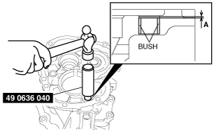
4x4
1. Install the bush using the SST.
Front side
bms1zm00000117
|
Rear side
bms1zm00000118
|
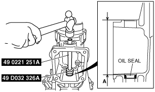
Oil Seal (control rod) Assembly Note
4x2
1. Apply specified grease to the lip of a new oil seal.
2. Install the oil seal using the SSTs through the sealing cap hole as shown in the figure.
bms1zm00000119
|
4x4
1. Apply specified grease to the lip of a new oil seal.
2. Install the oil seal using the SST.
bms1zm00000120
|
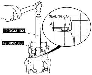
Sealing Cap Assembly Note
1. Install the sealing cap using the SSTs.
bms1zm00000121
|
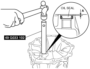
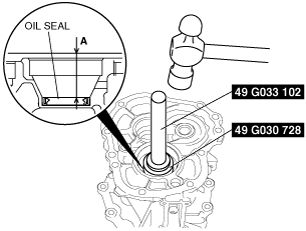
Oil Seal (Extension Housing) Assembly Note
1. Apply specified grease to the lip of a new oil seal.
2. Install the oil seal evenly and gradually using the SST and a hammer.
4x2
bms1zm00000122
|
4x4
bms1zm00000123
|
Extension Housing Assembly Note
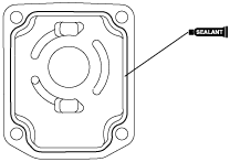
1. Apply sealant to the contact surfaces of the extension housing and transmission case as shown in the figure.
bms1zm00000124
|
2. Install the extension housing to the transmission case.
Top Cover Assembly Note
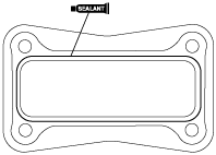
1. Apply sealant to the contact surfaces of the transmission case and top cover as shown in the figure.
bms1zm00000125
|
2. Install the top cover component to the transmission case.
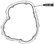
Control Case Assembly Note
1. Apply sealant to the contact surfaces of the control case and extension housing as shown in the figure.
bms1zm00000126
|
2. Install the control case to the extension housing.
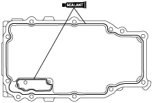
Blind Cover Assembly Note
1. Apply sealant to the contact surfaces of the blind cover and extension housing as shown in the figure.
bms1zm00000127
|
2. Install the blind cover to the extension housing.
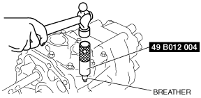
Breather Assembly Note
1. Install the new breather using the SST.
bms1zm00000128
|
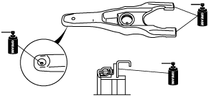
Release Collar, Release Fork Assembly Note
1. Apply specified grease to the areas shown in the figure.
bms1zm00000129
|
2. Install the release collar and release fork.