 |
bms1zm00000235
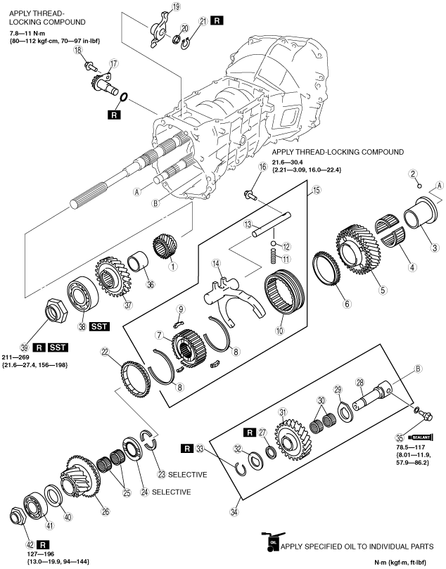
5TH/REVERSE GEAR COMPONENT ASSEMBLY
id051100520600
1. Assemble in the order indicated in the table.
bms1zm00000235
|
|
1
|
5th counter gear
|
|
2
|
Steel ball
|
|
3
|
5th gear bearing inner race
|
|
4
|
Needle bearing
|
|
5
|
5th gear
|
|
6
|
Synchronizer ring
|
|
7
|
5th/reverse clutch hub
|
|
8
|
Synchronizer key spring
|
|
9
|
Synchronizer key
|
|
10
|
Clutch hub sleeve
|
|
11
|
Detent spring
|
|
12
|
Detent ball
|
|
13
|
5th/reverse shift rod
|
|
14
|
5th/reverse shift fork
|
|
15
|
5th/reverse clutch hub and shift fork component
|
|
16
|
Retaining bolt
|
|
17
|
Counter lever shaft component
|
|
18
|
Retaining bolt
|
|
19
|
Counter lever
|
|
20
|
Washer
|
|
21
|
Retaining ring
|
|
22
|
Thrust washer
|
|
23
|
Thrust washer
|
|
24
|
Spacer
|
|
25
|
Needle bearing
|
|
26
|
Reverse gear
(See Reverse Gear Assembly Note.)
|
|
27
|
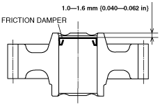
Friction damper
|
|
28
|
Reverse idler gear shaft
|
|
29
|
Thrust washer
|
|
30
|
Needle bearing
|
|
31
|
Reverse idler gear
|
|
32
|
Thrust washer
|
|
33
|
Retaining ring
|
|
34
|
Reverse idler gear shaft component
|
|
35
|
Retaining bolt
|
|
36
|
Spacer
|
|
37
|
Reverse counter gear
|
|
38
|
Mainshaft rear bearing
|
|
39
|
Locknut
|
|
40
|
Thrust washer
|
|
41
|
Countershaft rear bearing
|
|
42
|
Locknut
|
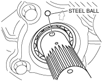
5th Gear Bearing Inner Race Assembly Note
1. Install the steel ball to the countershaft.
bms1zm00000147
|
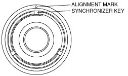
2. Align the ball groove position of the 5th gear bearing inner race and assemble it to the countershaft.
5th Counter Gear, 5th/Reverse Clutch Hub Component and 5th/Reverse Shift Fork Assembly Note
1. Assemble the 5th drive gear and 5th/reverse clutch hub component.
bms1zm00000148
|
|
|
A |
B |
C |
|---|---|---|---|
|
5th/6th
|
18.0 {0.709}
|
5.45 {0.215}
|
6.0 {0.236}
|
bms1zm00000149
|
2. Assemble the 5th counter gear component, 5th/reverse clutch hub component, and 5th/reverse shift fork component as a single unit.
bms1zm00000150
|
3. Install the 5th/reverse shift rod retaining bolt.
bms1zm00000151
|
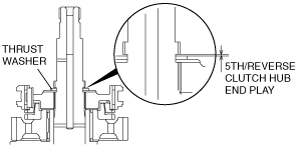
4. Install the thrust washer.
5. Measure the clearance between thrust washer and groove of the countershaft.
bms1zm00000152
|
5th/Reverse clutch hub thrust washer
|
Thickness (mm {in}) |
|---|
|
3.00 {0.118}
|
|
3.05 {0.120}
|
|
3.10 {0.122}
|
|
3.15 {0.124}
|
|
3.20 {0.126}
|
|
3.25 {0.128}
|
|
3.30 {0.130}
|
|
3.35 {0.132}
|
|
3.40 {0.134}
|
Reverse Gear Assembly Note
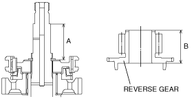
1. Measure the clearance A and B.
bms1zm00000153
|
Reverse gear spacer
|
Dimension C (mm {in}) |
Thickness (mm {in}) |
|---|---|
|
7.60—7.70
{0.300—0.303}
|
7.35 {0.289}
|
|
7.70—7.80
{0.304—0.307}
|
7.45 {0.293}
|
|
7.80—7.90
{0.308—0.311}
|
7.55 {0.297}
|
|
7.90—8.00
{0.312—0.314}
|
7.65 {0.301}
|
|
8.00—8.10
{0.315—0.318}
|
7.75 {0.305}
|
2. Install the spacer.
3. Install the reverse gear.
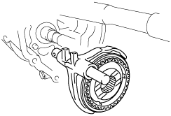
Counter Lever Shaft Assembly Note
1. Install the counter lever shaft component.
bms1zm00000154
|
Reverse Idler Gear Component Assembly Note
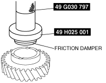
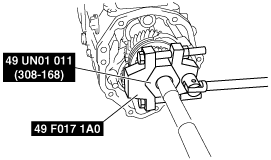
1. Using the SSTs, install the friction damper to the reverse idler gear.
bms1zm00000155
|
bms1zm00000156
|
2. Assemble the reverse idler gear component.
3. Measure the clearance between the retaining ring and thrust washer.
bms1zm00000157
|
Reverse idler gear retaining ring
|
Thickness (mm {in}) |
|---|
|
1.5 {0.059}
|
|
1.6 {0.063}
|
|
1.7 {0.067}
|
|
1.8 {0.071}
|
|
1.9{0.075}
|
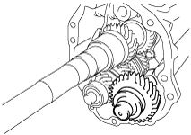
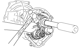
4. Install the reverse idler gear component to the transmission case.
bms1zm00000158
|
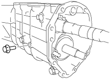
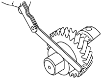
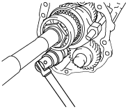
5. Install the reverse idler gear shaft retaining bolt.
bms1zm00000159
|
Mainshaft Rear Bearing and Countershaft Rear Bearing Locknut Assembly Note
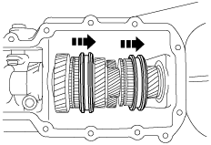
1. Slide the 3rd/4th and 1st/2nd clutch hub sleeves to lock the transmission into 4th and 2nd gears.
bms1zm00000160
|
2. Insert the mainshaft rear bearing into the mainshaft and install the locknut.
3. Attach the SST to the locknut and tighten the nut to the specified torque.
bms1zm00000161
|
4. Tighten the countershaft locknut in the counterclockwise direction.
bms1zm00000162
|
5. Using the pin punch, stake the mainshaft rear bearing locknut.
bms1zm00000163
|
6. Using the pin punch, stake the countershaft rear bearing locknut.
bms1zm00000164
|