 |
b5r5za00000446
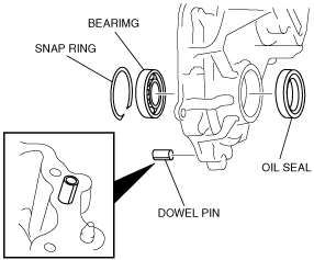
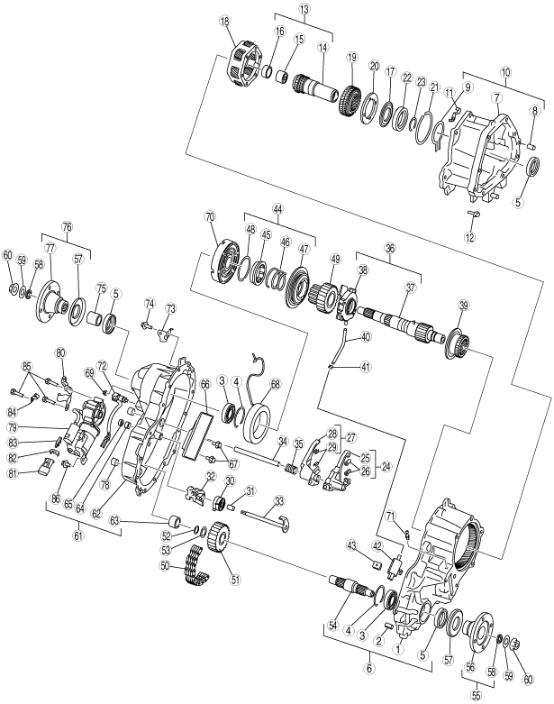
TRANSFER CASE ASSEMBLY
id031600501200
Exploded View
b5r5za00000446
|
|
1
|
Center transfer case
|
|
2
|
Dowel pin
|
|
3
|
Bearing
|
|
4
|
Snap ring
|
|
5
|
Oil seal
|
|
6
|
Center transfer case component
|
|
7
|
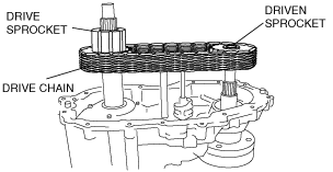
Front transfer case
|
|
8
|
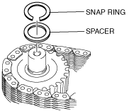
Dowel pin
|
|
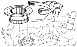
9
|
Snap ring
|
|
10
|
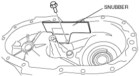
Front transfer case component
|
|
11
|
Clip
|
|
12
|
Bolt
|
|
13
|
Input shaft component
|
|
14
|
Input shaft
|
|
15
|
Needle bearing
|
|
16
|
Bushing
|
|
17
|
Thrust washer
|
|
18
|
Planetary gear component
|
|
19
|
Sun gear
|
|
20
|
Thrust plate
|
|
21
|
Snap ring A
|
|
22
|
Ball bearing
|
|
23
|
Snap ring B
|
|
24
|
Reduction shift fork component
|
|
25
|
Reduction shift fork
|
|
26
|
Reduction shift fork facing
|
|
27
|
Lockup shift fork component
|
|
28
|
Lockup shift fork
|
|
29
|
Lockup shift fork facing
|
|
30
|
Spring
|
|
31
|
Spacer
|
|
32
|
Cam
|
|
33
|
Shift shaft
|
|
34
|
Rail shift
|
|
35
|
Return spring
|
|
36
|
Output shaft and gerotor pump component
|
|
37
|
Output shaft component
|
|
38
|
Gerotor pump component
|
|
39
|
Reduction hub
|
|
40
|
Pump hose
|
|
41
|
Hose clamp
|
|
42
|
Oil strainer
|
|
43
|
Magnet
|
|
44
|
Lockup component
|
|
45
|
Lockup hub
|
|
46
|
Spring
|
|
47
|
Lockup collar
|
|
48
|
Snap ring
|
|
49
|
Drive sprocket
|
|
50
|
Drive chain
|
|
51
|
Driven sprocket
|
|
52
|
Snap ring
|
|
53
|
Spacer
|
|
54
|
Lower output shaft
|
|
55
|
Front output flange component
|
|
56
|
Front output flange
|
|
57
|
Deflector
|
|
58
|
Oil seal
|
|
59
|
Washer
|
|
60
|
Locknut
|
|
61
|
Rear transfer case component
|
|
62
|
Rear transfer case
|
|
63
|
Needle bearing
|
|
64
|
Sleeve
|
|
65
|
Seal
|
|
66
|
Snubber
|
|
67
|
Bolt
|
|
68
|
Clutch coil
|
|
69
|
Nut
|
|
70
|
Clutch housing
|
|
71
|
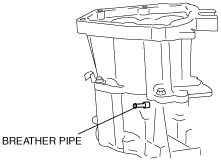
Breather pipe
|
|
72
|
Speed sensor component
|
|
73
|
Bracket
|
|
74
|
Bolt
|
|
75
|
Spacer
|
|
76
|
Rear companion flange component
|
|
77
|
Rear companion flange
|
|
78
|
Oil plug
|
|
79
|
Motor component
|
|
80
|
Bracket
|
|
81
|
Terminal connector
|
|
82
|
Clip
|
|
83
|
Bracket
|
|
84
|
Clip
|
|
85
|
Bolt
|
|
86
|
Bolt
|
Assembly Procedure
1. Insert two new dowel pins.
b5r5za00000410
|
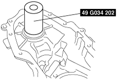
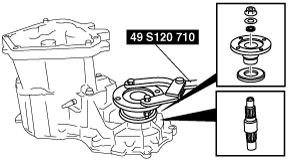
2. Press the ball bearing into the center transfer case using the SST.
b5r5za00000503
|
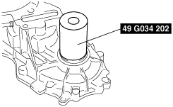
3. Install the snap ring.
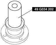
4. Install the new oil seal, by pressing it into the center transfer case using the SST.
b5r5za00000488
|
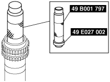
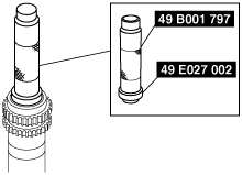
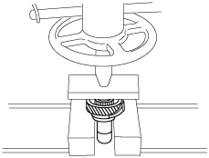
5. Press the new needle bearing into the input shaft using the SST.
b5r5za00000489
|
6. Press the new bushing into the input shaft using the SST.
b5r5za00000490
|
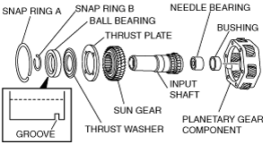
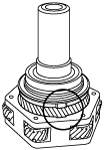
7. Assemble the sun gear and thrust plate to the input shaft.
b5r5za00000505
|
8. Assemble the thrust washer and ball bearing to the input shaft using the press.
b5r5za00000478
|
9. Install the snap ring B.
10. Assemble the planetary gear component to the planet carrier as shown in the figure.
b5r5za00000329
|
11. Install the snap ring A to the planetary gear component.
12. Press the new oil seal into the front transfer case using the SST.
b5r5za00000491
|
13. Install the snap ring by making sure that the snap ring is correctly installed into the groove.
b5r5za00000331
|
14. Place the input shaft component onto the front transfer case, and assemble the planetary gear component to the groove while expanding the ends of the snap ring.
b5r5za00000479
|
15. Apply sealant to the front transfer case as shown in the figure.
b5r5za00000333
|
16. Install the front transfer case on the center transfer case.
arnffv00000620
|
17. Install the six bolts and clip.
18. Install the breather pipe on the center transfer case.
b5r5za00000422
|
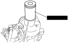
19. Press in the new deflector to the flange using the SST.
b5r5za00000492
|
20. Assemble the lower output shaft to the center transfer case.
b5r5za00000501
|
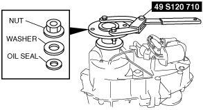
21. Assemble the front output flange component, oil seal, washer, and nut.
22. Secure the flange using the SST.
23. Tighten the nut.
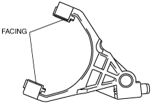
24. Install the two-fork facing on the reduction shift fork component.
b5r5za00000438
|
25. Install the reduction hub to the shift fork.
b5r5za00000336
|
26. Install the reduction hub and shift fork component to the planetary gear component.
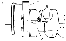
27. Insert the spacer torsion spring and cam into the shift shaft.
b5r5za00000439
|
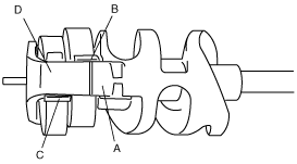
28. Press them in until area A of the cam contacts area B of the torsion spring, and area C of the torsion spring contacts area D of the shift shaft.
b5r5za00000440
|
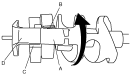
29. Rotate the cam to the position indicated in the figure, and press it to the shift shaft side until it contacts the torsion spring.
b5r5za00000441
|
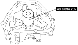
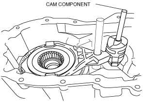
30. Install the cam component in the case as shown in the picture.
b5r5za00000417
|
31. Verify that the reduction fork roller is seated in the cam groove as shown in the figure.
32. Assemble the rail shift to the reduction fork bore.
33. Using a hose clamp, tighten the pump hose at the end where it is coupled with the strainer.
b5r5za00000452
|
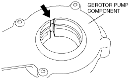
34. Align the gerotor pump rotor slot and the pump body slot so that they are in a single line.
arnffv00000598
|
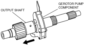
35. Slide the gerotor pump component on the output shaft over pump pin.
b5r5za00000419
|
36. Assemble the output shaft from the center transfer case.
b5r5za00000453
|
37. Assemble the output shaft spline to the reduction hub.
38. Engage the output shaft end with the input shaft bearing.
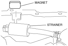
39. Couple the strainer with the case and insert the magnet into the transfer case slot.
b5r5za00000451
|
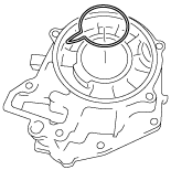
40. Assemble the drive sprocket to the output shaft.
41. Assemble the lower output shaft to the driven sprocket.
42. Install the drive chain onto the sprockets.
b5r5za00000406
|
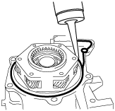
43. While keeping the tension of the drive chain, assemble the transfer case and drive chain component in parallel.
44. While rotating the driven sprocket, engage it with the front output shaft spline.
45. Assemble the spacer to the front output shaft.
b5r5za00000450
|
46. Assemble the snap ring into the groove.
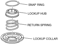
47. Install the lockup hub and return spring to the lock up collar and insert the snap ring.
b5r5za00000449
|
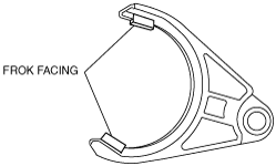
48. Install the two new facings to the fork.
b5r5za00000414
|
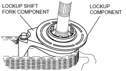
49. Assemble the lockup component to the lockup fork, and assemble them to the drive shaft and the rail shaft.
b5r5za00000448
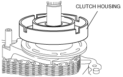
|
50. Install the clutch housing on the output shaft.
b5r5za00000312
|
51. Position the end of the new needle bearing with the identification mark facing upwards and press it into the cover using the SST.
b5r5za00000504
|
52. Press the ball bearing into the rear transfer case using the SST and install the snap ring.
b5r5za00000494
|
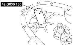
53. Install the coil inside the rear transfer case.
b5r5za00000310
|
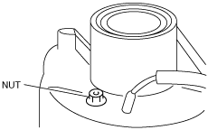
54. Install the three nuts.
55. Install the snubber.
b5r5za00000412
|
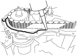
56. Install the return spring over rail shaft in the rear transfer case.
57. Apply a 1.6 mm {0.063 in} bead of sealant to the transfer case mounting surface, and assemble the cover and the transfer case.
b5r5za00000350
|
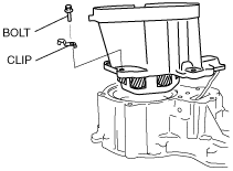
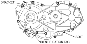
58. Install the rear transfer case onto the center transfer case as follows.
59. Install the 14 bolts, identification tag and bracket.
b5r5za00000429
|
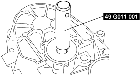
60. Using the SST, install the new oil seal.
b5r5za00000495
|
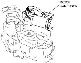
61. Align the motor component with the shift shaft and assemble it to the rear transfer case.
arnffv00000615
|
62. Rotate the motor in clockwise direction to check correct engagement.
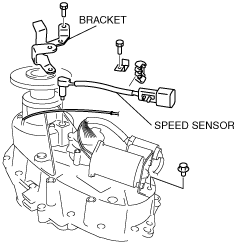
63. Install the speed sensor in the rear transfer case.
arnffv00000622
|
64. Install the bracket and bolts to the motor component.
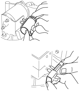
65. Pass the clutch coil wiring harness through the sensor harness sleeve, and connect the coil terminal to the connector.
b5r5za00000352
|
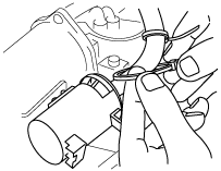
66. Install the motor connector and sensor connector to the motor bracket.
67. Bundle the wiring harness between the speedometer component and terminal connector using a wiring harness protector and tie wraps.
b5r5za00000353
|
68. Install the oil plug to the rear transfer case.
69. Install the spacer over output shaft spline.
b5r5za00000454
|
70. Press the new oil seal into the rear transfer case component using the SST.
b5r5za00000496
|
71. Press in the new deflector to the flange using the SST.
b5r5za00000492
|
72. Install the rear companion flange component, oil seal, washer and nut.
b5r5za00000502
|
73. Holding the rear companion flange using the SST, tighten the nut.