 |
b5r5za00000382
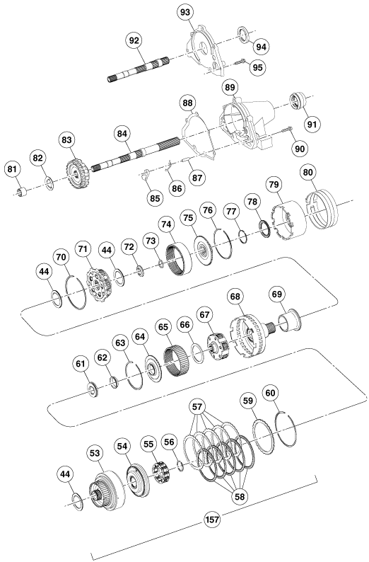
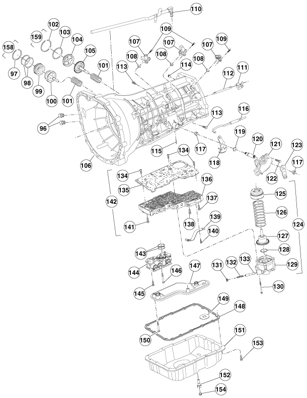
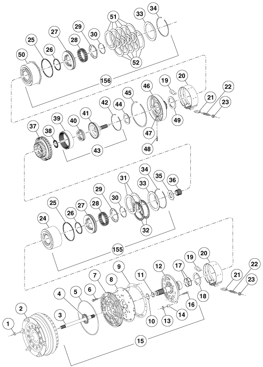
AUTOMATIC TRANSMISSION DISASSEMBLY
id051300260100
Exploded View
b5r5za00000382
|
b5r5za00000383
|
b5r5za00000384
|
|
1
|
Torque converter installation nut
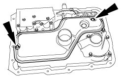
|
|
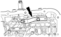
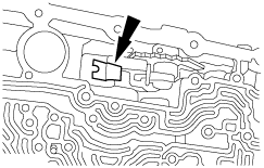
2
|
Torque converter
|
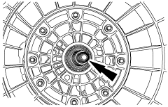
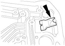
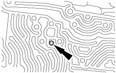
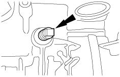
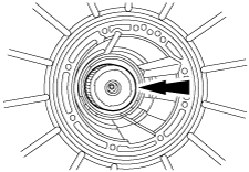
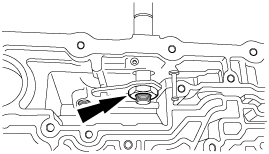
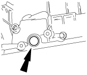
|
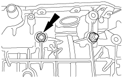
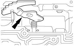
3
|
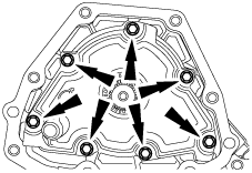
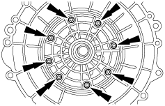
Input shaft
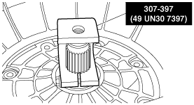
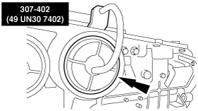
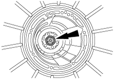
|
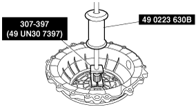
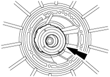
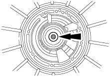
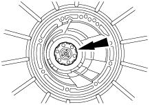
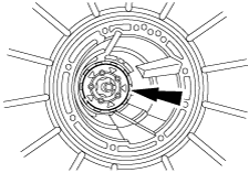
|
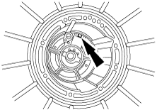
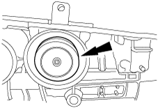
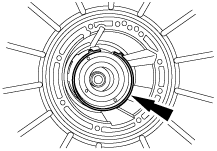
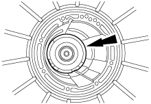
4
|
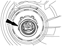
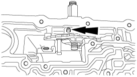
Fluid pump seal
|
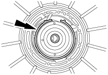
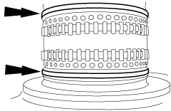
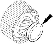
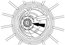
|
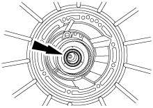
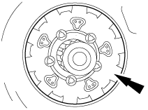
5
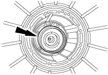
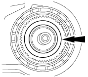
|
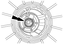
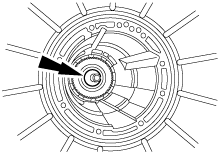
Fluid pump seal ring
|
|
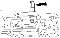
6
|
Bolt and washer
|
|
7
|
Fluid pump cover
|
|
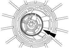
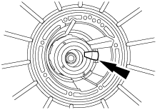
8
|
Fluid pump adapter plate
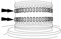
|
|
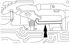
9
|
Fluid pump gasket
|
|
10
|
Seal ring
|
|
11
|
Stator support seal
|
|
12
|
Fluid pump support
|
|
13
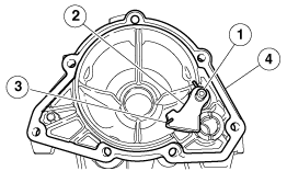
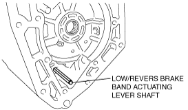
|
O-ring
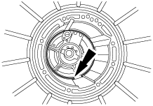
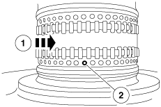
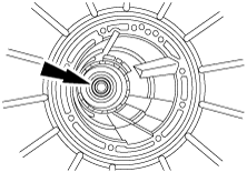
|
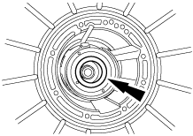
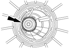
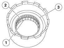
|
14
|
Fluid pump control valve
|
|
15
|
Fluid pump component
|
|
16
|
Bolt
|
|
17
|
Seal ring
|
|
18
|
Thrust washer (No.1)
|
|
19
|
Intermediate and overdrive brake band anchor strut
|
|
20
|
Intermediate and overdrive brake band
|
|
21
|
Intermediate and overdrive brake band apply strut
|
|
22
|
Intermediate and overdrive brake band adjusting screw
|
|
23
|
Locknut
|
|
24
|
Overdrive brake drum
|
|
25
|
Direct clutch and coast clutch piston outer seals
|
|
26
|
Direct clutch and coast clutch piston inner seals
|
|
27
|
Direct clutch and coast clutch pistons
|
|
28
|
Direct clutch and coast clutch piston spring
|
|
29
|
Direct clutch and coast clutch piston spring retainer
|
|
30
|
Retaining ring
|
|
31
|
Coast clutch external spline plate (steel)
|
|
32
|
Coast clutch internal spline friction plate (friction)
|
|
33
|
Direct clutch and coast clutch pressure plate
|
|
34
|
Retaining ring (select fit)
|
|
35
|
Carrier adapter
|
|
36
|
Overdrive sun gear
|
|
37
|
Overdrive planetary gear carrier component
|
|
38
|
Thrust bearing (No.2)
|
|
39
|
Overdrive ring gear
|
|
40
|
Overdrive one-way clutch
|
|
41
|
Overdrive center shaft
|
|
42
|
Retaining ring
|
|
43
|
Overdrive center shaft and ring gear component
|
|
44
|
Thrust bearing (No.3, No.5, No.8 and No.9)
|
|
45
|
Retaining ring
|
|
46
|
Center support
|
|
47
|
Nut and cage component
|
|
48
|
Bolt
|
|
49
|
Thrust bearing (No.4)
|
|
50
|
Intermediate brake drum
|
|
51
|
Direct clutch external spline plate (steel)
|
|
52
|
Direct clutch internal spline plate (friction)
|
|
53
|
Forward clutch cylinder
|
|
54
|
Forward clutch piston
|
|
55
|
Forward clutch piston spring component
|
|
56
|
Retaining ring
|
|
57
|
Forward clutch external spline plate (steel)
|
|
58
|
Forward clutch internal spline plate (friction)
|
|
59
|
Forward clutch pressure plate
|
|
60
|
Retaining ring (select fit)
|
|
61
|
Thrust bearing (No.6A)
|
|
62
|
Thrust washer (No.6B)
|
|
63
|
Retaining ring
|
|
64
|
Forward ring gear hub
|
|
65
|
Forward ring gear
|
|
66
|
Thrust bearing (No.7)
|
|
67
|
Forward planetary component
|
|
68
|
Input shell and sun gear component
|
|
69
|
Spacer
|
|
70
|
Retaining ring
|
|
71
|
Lower/reverse planetary component
|
|
72
|
Output shaft sleeve
|
|
73
|
Retaining ring
|
|
74
|
Output shaft ring gear
|
|
75
|
Output shaft hub
|
|
76
|
Retaining ring
|
|
77
|
Output shaft hub seal
|
|
78
|
Thrust bearing (No.10)
|
|
79
|
Low/reverse brake drum and one-way clutch component
|
|
80
|
Low/reverse brake band
|
|
81
|
Output shaft needle bearing
|
|
82
|
Thrust washer (No.11)
|
|
83
|
Parking gear
|
|
84
|
Output shaft (4×2)
|
|
85
|
Parking pawl
|
|
86
|
Parking pawl return spring
|
|
87
|
Parking pawl shaft
|
|
88
|
Extension housing gasket
|
|
89
|
Extension housing (4×2)
|
|
90
|
Bolt (4×2)
|
|
91
|
Extension housing seal (4×2)
|
|
92
|
Output shaft (4×4)
|
|
93
|
Extension housing (4×4)
|
|
94
|
Extension housing seal (4×4)
|
|
95
|
Bolt (4×4)
|
|
96
|
Fluid pipe connector component
|
|
97
|
Retaining ring
|
|
98
|
Overdrive brake servo cover seal
|
|
99
|
Overdrive brake servo cover
|
|
100
|
Overdrive brake servo piston
|
|
101
|
Spring
|
|
102
|
Retaining ring
|
|
103
|
Intermediate brake servo cover seal
|
|
104
|
Intermediate brake servo cover
|
|
105
|
Intermediate brake servo piston
|
|
106
|
Transmission case
|
|
107
|
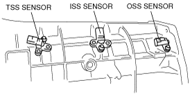
TSS sensor, ISS sensor and OSS sensor
|
|
108
|
O-ring
|
|
109
|
Bolt
|
|
110
|
Vent tube (4×2)
|
|
111
|
Low/reverse brake actuating lever
|
|
112
|
Low/reverse brake band actuating lever shaft
|
|
113
|
Pressure tap plug (pressure control solenoid C circuit)
|
|
114
|
Fluid fill plug
|
|
115
|
Manual shaft retaining pin
|
|
116
|
Parking pawl actuating rod
|
|
117
|
Manual shaft outer and inner nut
|
|
118
|
Manual valve inner lever
|
|
119
|
Manual shaft seal
|
|
120
|
Manual shaft
|
|
121
|
Digital TR sensor
|
|
122
|
Bolt and washer
|
|
123
|
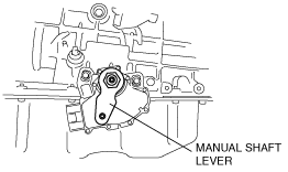
Manual shaft lever
|
|
124
|
Reverse brake servo component
|
|
125
|
Reverse brake servo plate
|
|
126
|
Spring
|
|
127
|
Reverse brake servo piston and seal
|
|
128
|
O-ring
|
|
129
|
Reverse brake servo cover
|
|
130
|
Bolt
|
|
131
|
Control valve spring retainer
|
|
132
|
Spring
|
|
133
|
Reverse brake servo check valve
|
|
134
|
Bolt
|
|
135
|
Separating plate (bonded)
|
|
136
|
Lower control valve body
|
|
137
|
Bolt
|
|
138
|
Bolt
|
|
139
|
Detent spring
|
|
140
|
Bolt
|
|
141
|
Bolt
|
|
142
|
Control valve body component
|
|
143
|
O-ring
|
|
144
|
Solenoid body
|
|
145
|
Bolt
|
|
146
|
Bolt
|
|
147
|
Transmission fluid filter
|
|
148
|
Transmission fluid pan gasket
|
|
149
|
Magnet
|
|
150
|
Bolt
|
|
151
|
Transmission fluid pan
|
|
152
|
Drain plug
|
|
153
|
Bolt
|
|
154
|
Fluid level indicating plug (short hex)
|
|
155
|
Overdrive brake and coast clutch drum component
|
|
156
|
Intermediate brake and direct clutch drum component
|
|
157
|
Forward clutch component
|
|
158
|
Overdrive brake servo
|
|
159
|
Intermediate brake servo
|
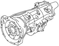
1. Place the transmission on a workbench.
arnffv00000559
|
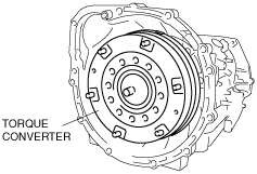
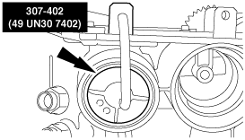
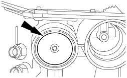
2. Remove the torque converter.
b5r5za00000361
|
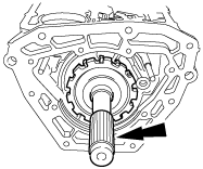
3. Remove the input shaft.
b5r5za00000005
|
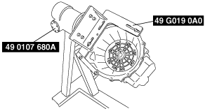
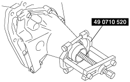
4. Install the SST (49 G019 0A0) to the transmission.
b5r5za00000531
|
5. Install the transmission with the torque converter housing facing up to the SST (49 0107 680A).
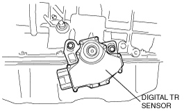
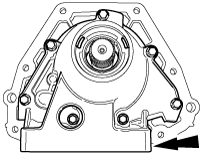
6. Remove the sensors.
b5r5za00000363
|
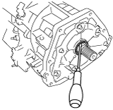
7. Remove the manual shaft lever.
b5r5za00000364
|
8. Remove the digital TR sensor.
b5r5za00000365
|
9. Using a flathead screwdriver, lift up the extension housing seal plate area.
b5r5za00000366
|
10. Using the SST, remove the extension housing seal. (4×2)
b5r5za00000367
|
11. Remove the extension housing. (4×2)
b5r5za00000011
|
12. Using a flathead screwdriver, remove the extension housing seal. (4×4)
b5r5za00000537
|
13. Remove the extension housing. (4×4)
b5r5za00000012
|
14. Remove the parking pawl component and discard the gasket.
b5r5za00000013
|
15. Remove the transmission fluid pan screws, transmission fluid pan and gasket.
b5r5za00000014
|
16. Remove the transmission fluid filter and seal component and discard.
b5r5za00000015
|
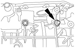
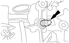
17. Remove the detent spring.
b5r5za00000016
|
18. Remove the low/reverse brake servo component.
b5r5za00000017
|
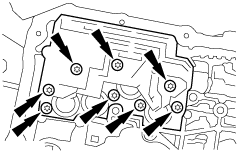
19. Remove the solenoid body component by lifting on the body and pushing the connector from the other side of the case.
b5r5za00000018
|
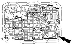
20. Remove the main control valve body, separator plate and gasket.
b5r5za00000019
|
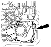
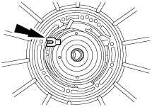
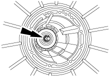
21. Using a flathead screwdriver, remove the fluid pump seal.
absggw00001936
|
22. Remove and discard the locknut, and loosen the overdrive brake band adjusting screw.
b5r5za00000021
|
23. Remove and tag the overdrive brake band anchor strut for assembly.
b5r5za00000022
|
24. Remove and discard the screws.
b5r5za00000023
|
25. Install the SST.
b5r5za00000509
|
26. Using the SST, remove the fluid pump.
b5r5za00000510
|
27. Using the SST, remove the retaining ring and overdrive brake servo cover.
b5r5za00000511
|
28. Remove the overdrive brake servo piston and spring.
b5r5za00000029
|
29. Remove the screw.
b5r5za00000030
|
30. Compress the overdrive brake band and remove the apply strut.
b5r5za00000031
|
31. Remove and inspect the overdrive brake band. Check the following conditions for installing a new band:
b5r5za00000032
|
32. Remove the overdrive brake and coast clutch drum component.
b5r5za00000033
|
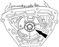
33. Remove the overdrive planetary gear carrier.
b5r5za00000034
|
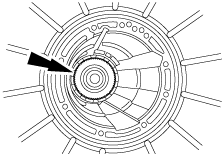
34. Remove the thrust bearing (No.2).
b5r5za00000035
|
35. Remove the overdrive ring gear, overdrive one-way clutch component and center shaft as an assembly.
b5r5za00000036
|
36. Remove the thrust bearing (No.3).
b5r5za00000037
|
37. Remove the screw.
b5r5za00000038
|
38. Remove the nut and cage.
b5r5za00000039
|
39. Remove the retaining ring.
b5r5za00000040
|
40. Remove the center support.
b5r5za00000041
|
41. Inspect the center support component for wear or damage.
b5r5za00000042
|
42. Inspect the seal rings for damage.
b5r5za00000043
|
43. Inspect the bearing for missing rollers or damage.
b5r5za00000044
|
44. Inspect the direct clutch feed hole for blockage or damage.
b5r5za00000045
|
45. Remove the thrust bearing (No.4).
b5r5za00000046
|
46. Remove and discard the locknut, and loosen the intermediate brake band adjusting screw.
b5r5za00000397
|
47. Using the SST, remove the retaining ring and intermediate brake servo cover.
b5r5za00000512
|
48. Remove the intermediate brake servo piston and spring.
b5r5za00000027
|
49. Remove and tag the intermediate brake band anchor strut for assembly.
b5r5za00000047
|
50. Remove and inspect the intermediate brake band. Check the following conditions for installing a new band:
b5r5za00000048
|
51. Remove and tag the intermediate brake band apply strut for assembly.
b5r5za00000049
|
52. Remove the screw.
b5r5za00000050
|
53. Remove the intermediate brake and direct clutch drum component.
b5r5za00000051
|
54. Remove the thrust bearing (No.5), tag and identify.
b5r5za00000052
|
55. Remove the forward clutch cylinder.
b5r5za00000053
|
56. Remove the thrust bearing (No.6A).
b5r5za00000054
|
57. Remove the forward ring gear and hub as an assembly.
b5r5za00000055
|
58. Remove the thrust washer (No. 6B) from the forward ring gear hub.
b5r5za00000056
|
59. Remove the thrust bearing (No.7).
b5r5za00000057
|
60. Remove the forward planetary component.
b5r5za00000058
|
61. Remove the input shell and sun gear component.
b5r5za00000059
|
62. Remove the spacer.
b5r5za00000060
|
63. Remove the thrust bearing (No.8).
b5r5za00000061
|
64. Remove the retaining ring.
b5r5za00000062
|
65. Remove low/reverse planetary component.
b5r5za00000063
|
66. Remove the thrust bearing (No.9).
b5r5za00000064
|
67. Using a small pick, remove the output shaft sleeve.
b5r5za00000065
|
68. While holding the output shaft, remove and discard the retaining ring.
b5r5za00000066
|
69. Remove the output shaft and park gear.
b5r5za00000074
|
70. Remove the output shaft thrust washer.
b5r5za00000075
|
71. Remove the output shaft ring gear and hub.
b5r5za00000368
|
72. Remove the thrust bearing (No.10).
b5r5za00000369
|
73. Using a pair of vice grips, hold the flat spots on the low/reverse brake band actuating lever shaft, wiggle it back and forth and remove the low/reverse brake band actuating lever shaft.
b5r5za00000389
|
74. Remove the low/reverse brake band actuating lever component.
b5r5za00000070
|
75. Remove the low/reverse brake drum and one-way clutch component by rotating it clockwise.
b5r5za00000371
|
76. Inspect the low/reverse brake drum component and install a new low/reverse brake drum component if damaged.
b5r5za00000072
|
77. Remove the low/reverse brake band.
b5r5za00000073
|
78. Remove the nut.
b5r5za00000076
|
79. Remove the manual shaft retaining pin.
b5r5za00000077
|
80. Remove the manual shaft.
b5r5za00000078
|
81. Disconnect the manual valve inner lever from the parking lever actuating rod.
b5r5za00000079
|
82. Remove the manual valve inner lever.
b5r5za00000080
|
83. Remove the parking lever actuating rod.
b5r5za00000081
|
84. Remove the manual shaft seal.
b5r5za00000082
|