 |
b5r5za00000083
CONTROL VALVE BODY DISASSEMBLY/ASSEMBLY
id051300261800
b5r5za00000083
|
|
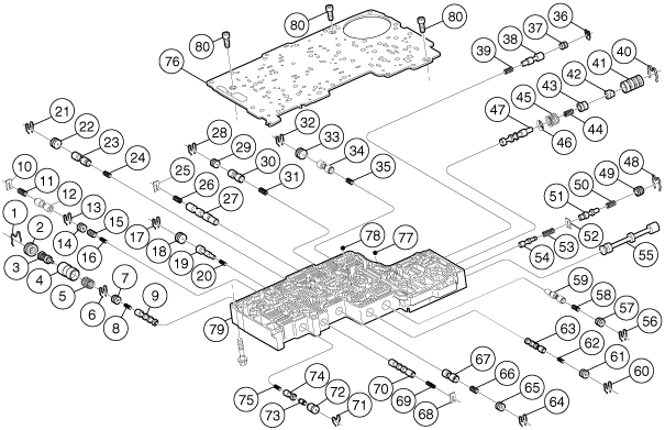
1
|
Retainer clip
|
|
2
|
Retainer plug
|
|
3
|
Thermo valve component
|
|
4
|
Fluid cooler bypass valve
|
|
5
|
Fluid cooler bypass spring
|
|
6
|
Retainer clip
|
|
7
|
Retainer plug
|
|
8
|
Converter clutch control valve spring
|
|
9
|
Converter clutch control valve
|
|
10
|
Plate
|
|
11
|
Coast clutch control spring
|
|
12
|
Coast clutch control valve
|
|
13
|
Retainer clip
|
|
14
|
Retainer plug
|
|
15
|
Converter clutch back pressure valve
|
|
16
|
Converter clutch back pressure spring
|
|
17
|
Retainer clip
|
|
18
|
Retainer plug
|
|
19
|
VFS2 modulator valve
|
|
20
|
VFS2 modulator valve spring
|
|
21
|
Retainer clip
|
|
22
|
Retainer plug
|
|
23
|
Intermediate servo release valve
|
|
24
|
Intermediate servo release valve spring
|
|
25
|
Plate
|
|
26
|
High clutch control spring
|
|
27
|
High clutch control Valve
|
|
28
|
Retainer plug
|
|
29
|
Retainer clip
|
|
30
|
Reverse modulator valve
|
|
31
|
Reverse modulator valve spring
|
|
32
|
Retainer clip
|
|
33
|
Retainer plug
|
|
34
|
Reverse engagement valve
|
|
35
|
Reverse engagement valve spring
|
|
36
|
Retainer clip
|
|
37
|
Retainer plug
|
|
38
|
VFS1 modulator valve
|
|
39
|
VFS1 modulator valve spring
|
|
40
|
Retainer clip
|
|
41
|
Sleeve
|
|
42
|
Booster valve
|
|
43
|
Booster valve
|
|
44
|
Inner spring
|
|
45
|
Outer spring
|
|
46
|
Retainer spring
|
|
47
|
Main regulator valve
|
|
48
|
Retainer clip
|
|
49
|
Retainer plug
|
|
50
|
Converter limit spring
|
|
51
|
Converter limit valve
|
|
52
|
Plate
|
|
53
|
Solenoid regulator valve spring
|
|
54
|
Solenoid regulator valve
|
|
55
|
Manual valve
|
|
56
|
Retainer clip
|
|
57
|
Retainer plug
|
|
58
|
Rear servo control valve spring
|
|
59
|
Rear servo control valve
|
|
60
|
Retainer clip
|
|
61
|
Retainer plug
|
|
62
|
RS ISA select valve spring
|
|
63
|
RS ISA select valve
|
|
64
|
Retainer clip
|
|
65
|
Retainer plug
|
|
66
|
Forward engagement control valve spring
|
|
67
|
Forward engagement control valve
|
|
68
|
Plate
|
|
69
|
Overdrive servo control spring
|
|
70
|
Overdrive servo control valve
|
|
71
|
Clip retainer
|
|
72
|
Converter clutch modulator control sleeve
|
|
73
|
Converter clutch modulator control valve
|
|
74
|
Converter clutch modulator valve
|
|
75
|
Converter clutch modulator control spring
|
|
76
|
Separator plate
|
|
77
|
Lubrication check ball
|
|
78
|
Shuttle valve ball
|
|
79
|
Lower control valve body
|
|
80
|
Bolt
|
Disassembly
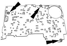
1. Remove and discard the separator plate.
b5r5za00000084
|
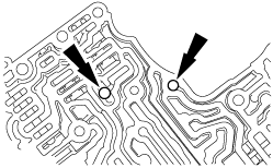
2. Remove the check balls.
b5r5za00000085
|
3. Disassemble the control valve body only if cleaning is required.
Assembly
1. Thoroughly clean all parts in solvent and blow dry with moisture-free compressed air.
2. After cleaning the control valve body, carry out the following:
3. Assemble the main control valve body.
4. Install the control valve body check balls.
b5r5za00000297
|
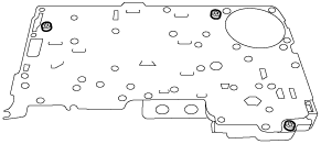
5. Install a new separator plate.
b5r5za00000381
|