 |
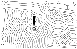
b5r5za00000382
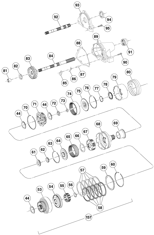
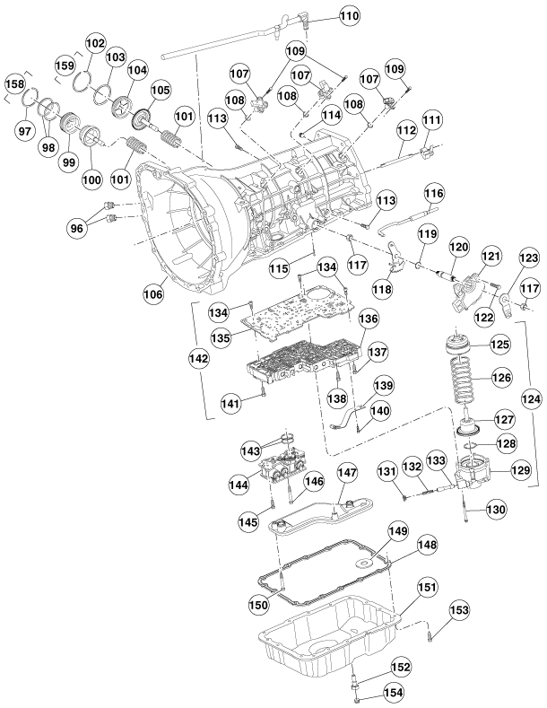
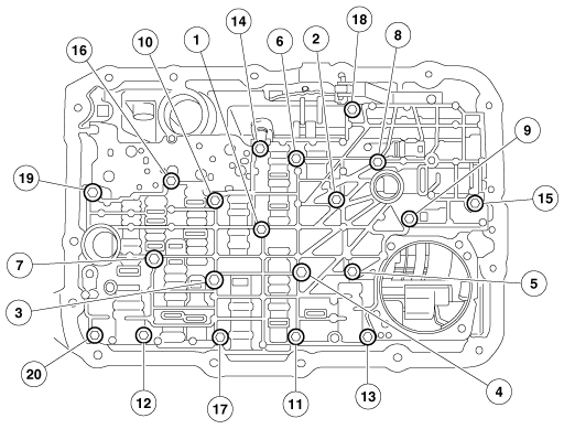
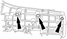
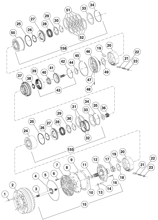
AUTOMATIC TRANSMISSION ASSEMBLY
id051300261900
Exploded View
b5r5za00000382
|
b5r5za00000383
|
b5r5za00000384
|
|
1
|
Torque converter installation nut
|
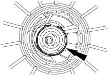
|
2
|
Torque converter
|
|
3
|
Input shaft
|
|
4
|
Fluid pump seal
|
|
5
|
Fluid pump seal ring
|
|
6
|
Bolt and washer
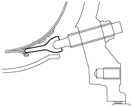
|
|
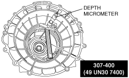
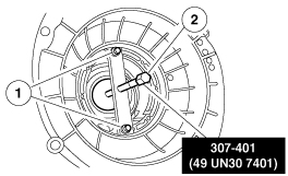
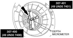
7
|
Fluid pump cover
|
|
8
|
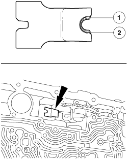
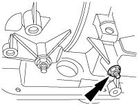
Fluid pump adapter plate
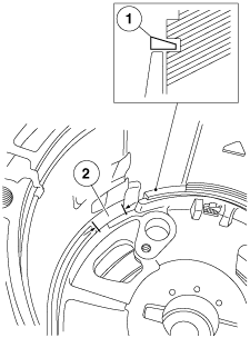
|
|
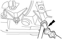
9
|
Fluid pump gasket
|
|
10
|
Seal ring
|
|
11
|
Stator support seal
|
|
12
|
Fluid pump support
|
|
13
|
O-ring
|
|
14
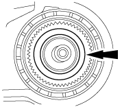
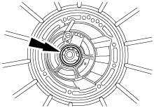
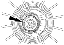
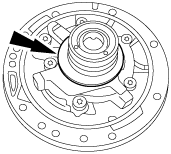
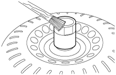
|
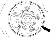
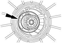
Fluid pump control valve
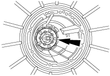
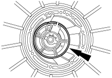
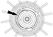
|
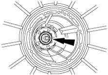
|
15
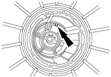
|
Fluid pump component
|
|
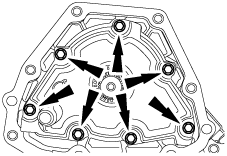
16
|
Bolt
|
|
17
|
Seal ring
|
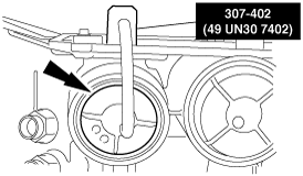
|
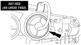
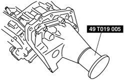
18
|
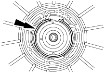
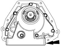
Thrust washer (No.1)
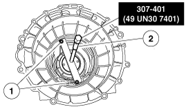
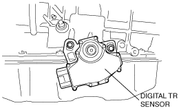
|
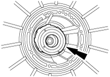
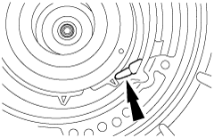
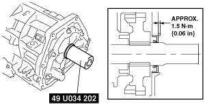
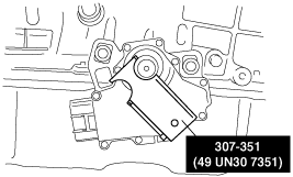
|
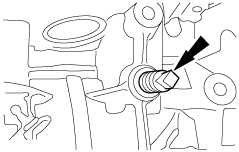
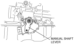
19
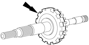
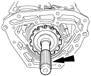
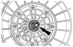
|
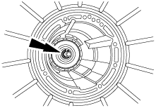
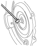
Intermediate and overdrive brake band anchor strut
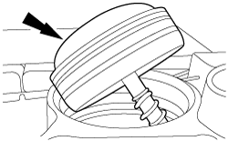
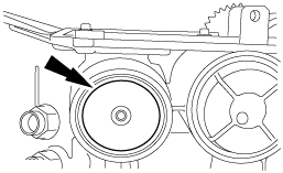
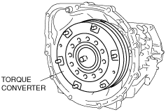
|
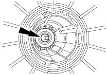
|
20
|
Intermediate and overdrive brake band
|
|
21
|
Intermediate and overdrive brake band apply strut
|
|
22
|
Intermediate and overdrive brake band adjusting screw
|
|
23
|
Locknut
|
|
24
|
Overdrive brake drum
|
|
25
|
Direct clutch and coast clutch piston outer seals
|
|
26
|
Direct clutch and coast clutch piston inner seals
|
|
27
|
Direct clutch and coast clutch pistons
|
|
28
|
Direct clutch and coast clutch piston spring
|
|
29
|
Direct clutch and coast clutch piston spring retainer
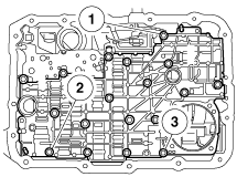
|
|
30
|
Retaining ring
|
|
31
|
Coast clutch external spline plate (steel)
|
|
32
|
Coast clutch internal spline friction plate (friction)
|
|
33
|
Direct clutch and coast clutch pressure plate
|
|
34
|
Retaining ring (select fit)
|
|
35
|
Carrier adapter
|
|
36
|
Overdrive sun gear
|
|
37
|
Overdrive planetary gear carrier component
|
|
38
|
Thrust bearing (No.2)
|
|
39
|
Overdrive ring gear
|
|
40
|
Overdrive one-way clutch
|
|
41
|
Overdrive center shaft
|
|
42
|
Retaining ring
|
|
43
|
Overdrive center shaft and ring gear component
|
|
44
|
Thrust bearing (No.3, No.5, No.8 and No.9)
|
|
45
|
Retaining ring
|
|
46
|
Center support
|
|
47
|
Nut and cage component
|
|
48
|
Bolt
|
|
49
|
Thrust bearing (No.4)
|
|
50
|
Intermediate brake drum
|
|
51
|
Direct clutch external spline plate (steel)
|
|
52
|
Direct clutch internal spline plate (friction)
|
|
53
|
Forward clutch cylinder
|
|
54
|
Forward clutch piston
|
|
55
|
Forward clutch piston spring component
|
|
56
|
Retaining ring
|
|
57
|
Forward clutch external spline plate (steel)
|
|
58
|
Forward clutch internal spline plate (friction)
|
|
59
|
Forward clutch pressure plate
|
|
60
|
Retaining ring (select fit)
|
|
61
|
Thrust bearing (No.6A)
|
|
62
|
Thrust washer (No.6B)
|
|
63
|
Retaining ring
|
|
64
|
Forward ring gear hub
|
|
65
|
Forward ring gear
|
|
66
|
Thrust bearing (No.7)
|
|
67
|
Forward planetary component
|
|
68
|
Input shell and sun gear component
|
|
69
|
Spacer
|
|
70
|
Retaining ring
|
|
71
|
Lower/reverse planetary component
|
|
72
|
Output shaft sleeve
|
|
73
|
Retaining ring
|
|
74
|
Output shaft ring gear
|
|
75
|
Output shaft hub
|
|
76
|
Retaining ring
|
|
77
|
Output shaft hub seal
|
|
78
|
Thrust bearing (No.10)
|
|
79
|
Low/reverse brake drum and one-way clutch component
|
|
80
|
Low/reverse brake band
|
|
81
|
Output shaft needle bearing
|
|
82
|
Thrust washer (No.11)
|
|
83
|
Parking gear
|
|
84
|
Output shaft (4×2)
|
|
85
|
Parking pawl
|
|
86
|
Parking pawl return spring
|
|
87
|
Parking pawl shaft
|
|
88
|
Extension housing gasket
|
|
89
|
Extension housing (4×2)
|
|
90
|
Bolt (4×2)
|
|
91
|
Extension housing seal (4×2)
|
|
92
|
Output shaft (4×4)
|
|
93
|
Extension housing (4×4)
|
|
94
|
Extension housing seal (4×4)
|
|
95
|
Bolt (4×4)
|
|
96
|
Fluid pipe connector component
|
|
97
|
Retaining ring
|
|
98
|
Overdrive brake servo cover seal
|
|
99
|
Overdrive brake servo cover
|
|
100
|
Overdrive brake servo piston
|
|
101
|
Spring
|
|
102
|
Retaining ring
|
|
103
|
Intermediate brake servo cover seal
|
|
104
|
Intermediate brake servo cover
|
|
105
|
Intermediate brake servo piston
|
|
106
|
Transmission case
|
|
107
|
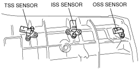
TSS sensor, ISS sensor and OSS sensor
|
|
108
|
O-ring
|
|
109
|
Bolt
|
|
110
|
Vent tube (4×2)
|
|
111
|
Low/reverse brake actuating lever
|
|
112
|
Low/reverse brake band actuating lever shaft
|
|
113
|
Pressure tap plug (pressure control solenoid C circuit)
|
|
114
|
Fluid fill plug
|
|
115
|
Manual shaft retaining pin
|
|
116
|
Parking pawl actuating rod
|
|
117
|
Manual shaft outer and inner nut
|
|
118
|
Manual valve inner lever
|
|
119
|
Manual shaft seal
|
|
120
|
Manual shaft
|
|
121
|
Digital TR sensor
|
|
122
|
Bolt and washer
|
|
123
|
Manual shaft lever
|
|
124
|
Reverse brake servo component
|
|
125
|
Reverse brake servo plate
|
|
126
|
Spring
|
|
127
|
Reverse brake servo piston and seal
|
|
128
|
O-ring
|
|
129
|
Reverse brake servo cover
|
|
130
|
Bolt
|
|
131
|
Control valve spring retainer
|
|
132
|
Spring
|
|
133
|
Reverse brake servo check valve
|
|
134
|
Bolt
|
|
135
|
Separating plate (bonded)
|
|
136
|
Lower control valve body
|
|
137
|
Bolt
|
|
138
|
Bolt
|
|
139
|
Detent spring
|
|
140
|
Bolt
|
|
141
|
Bolt
|
|
142
|
Control valve body component
|
|
143
|
O-ring
|
|
144
|
Solenoid body
|
|
145
|
Bolt
|
|
146
|
Bolt
|
|
147
|
Transmission fluid filter
|
|
148
|
Transmission fluid pan gasket
|
|
149
|
Magnet
|
|
150
|
Bolt
|
|
151
|
Transmission fluid pan
|
|
152
|
Drain plug
|
|
153
|
Bolt
|
|
154
|
Fluid level indicating plug (short hex)
|
|
155
|
Overdrive brake and coast clutch drum component
|
|
156
|
Intermediate brake and direct clutch drum component
|
|
157
|
Forward clutch component
|
|
158
|
Overdrive brake servo
|
|
159
|
Intermediate brake servo
|
Assembly
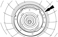
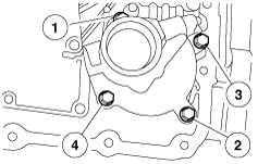
1. Thoroughly clean the transmission case and extension housing in solvent and blow dry with compressed air.
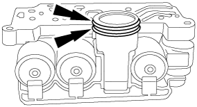
2. Inspect the transmission case for the following:
b5r5za00000186
|
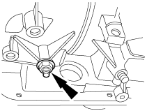
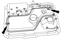
3. Inspect the extension housing for cracks, burrs or warpage.(4×2)
b5r5za00000187
|
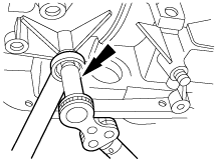
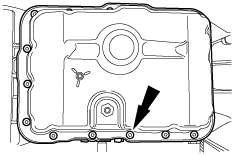
4. Inspect the extension housing for cracks, burrs or warpage.(4×4)
b5r5za00000188
|
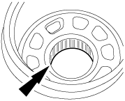
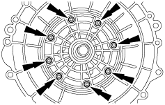
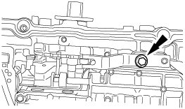
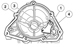
5. Inspect the case bearing for damage. If damage to the case bearing is indicated, install a new case.
b5r5za00000189
|
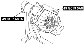
6. Using the SST, install the transmission into the bench with the converter housing facing up.
b5r5za00000532
|
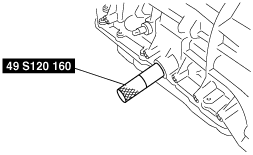
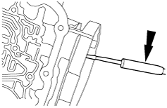
7. Using the SST, install the manual shaft seal and lubricate it with petroleum jelly.
b5r5za00000400
|
8. Install the parking lever rod.
b5r5za00000192
|
9. Install the manual control lever.
b5r5za00000193
|
10. Assemble the manual valve inner lever and parking lever actuating rod as shown.
b5r5za00000194
|
11. Install the manual shaft.
b5r5za00000195
|
12. Install the manual valve inner lever onto the manual shaft and loosely install the nut.
b5r5za00000196
|
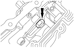
13. Install the manual shaft retaining pin.
b5r5za00000197
|
14. Tighten the nut.
b5r5za00000198
|
15. Install the low/reverse brake band.
b5r5za00000203
|
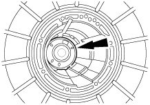
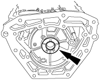
16. Install the low/reverse brake drum and one-way clutch component.
b5r5za00000388
|
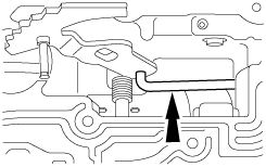
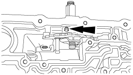
17. Install the low/reverse brake band actuating lever into the low/reverse brake band.
b5r5za00000204
|
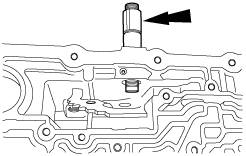
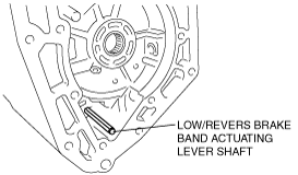
18. Install the low/reverse brake band actuating lever shaft into the case and into the low/reverse brake band actuating lever.
b5r5za00000389
|
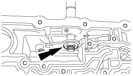
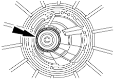
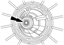
19. Install the thrust bearing (No.10) into the case.
b5r5za00000390
|
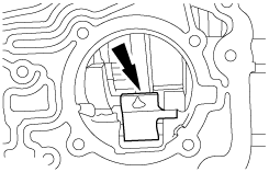
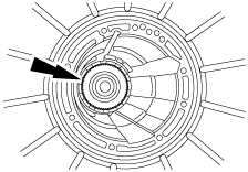
20. Install the output shaft ring gear, hub and seal.
b5r5za00000391
|
21. Install the output shaft thrust washer (No.11).
b5r5za00000199
|
22. Install the park gear on the output shaft.
b5r5za00000200
|
23. Install the output shaft and park gear.
b5r5za00000201
|
24. Install a new retaining ring.
b5r5za00000208
|
25. Install the output shaft sleeve.
b5r5za00000209
|
26. Install the thrust bearing (No.9) onto the output shaft ring gear and hub component.
b5r5za00000210
|
27. Install the low/reverse planetary component.
b5r5za00000211
|
28. Install the retaining ring.
b5r5za00000212
|
29. Install the thrust bearing (No.8).
b5r5za00000213
|
30. Install the spacer on the input shell, using petroleum jelly to hold it in place.
b5r5za00000214
|
31. Install the input shell and sun gear component.
b5r5za00000215
|
32. Install the forward planetary component.
b5r5za00000216
|
33. Install the thrust bearing (No.7) into the forward ring gear and hub component. Use petroleum jelly to hold the bearing in place.
b5r5za00000217
|
34. Install the thrust washer (No.6B) onto the forward ring gear hub.
b5r5za00000218
|
35. Install the forward ring gear and hub as an assembly.
b5r5za00000219
|
36. Install the thrust bearing (No.6A) into the forward ring gear and hub.
b5r5za00000220
|
37. Install the forward clutch cylinder.
b5r5za00000221
|
38. Install the thrust bearing (No.5).
b5r5za00000222
|
39. Install the intermediate brake servo piston and spring.
b5r5za00000223
|
40. Using the SST, install the intermediate brake servo cover and retaining ring.
b5r5za00000512
|
41. Install the intermediate brake and direct clutch drum component.
b5r5za00000225
|
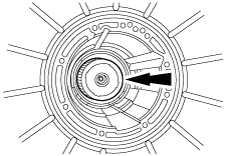
42. Using a depth micrometer with an appropriate length extension, measure from the top of the gauge bar to the center support ledge in the case at 4 places 90 degrees apart.
b5r5za00000513
|
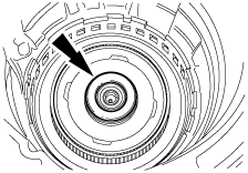
43. Install the SST.
b5r5za00000514
|
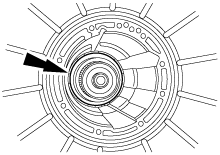
44. Measure the distance from the top of the gauge bar to the drum bearing surface through the hole in the disc and record as dimension B. Repeat the measurement 180 degrees on the opposite side of the SST and record as dimension C.
b5r5za00000515
|
45. Add dimension B to C, divide by 2 and record as dimension D.
46. Subtract A from D and record as dimension E.
47. Select the bearing from the following chart, using dimension E.
Thrust bearing (No.4) size (intermediate brake drum)
|
Dimension E |
Bearing Thickness |
Identification (Notches) |
|---|---|---|
|
1.69—1.87 mm {0.066—0.074 in}
|
2.65—2.80 mm {0.104—0.110 in}
|
None
|
|
1.88—2.04 mm {0.073—0.080 in}
|
2.83—2.98 mm {0.111—0.116 in}
|
1
|
|
2.05—2.22 mm {0.081— 0.088 in}
|
3.01—3.16 mm {0.118—0.124 in}
|
2
|
|
2.23—2.43 mm {0.088—0.096 in}
|
3.21—3.36 mm {0.126—0.132 in}
|
3
|
48. Install the intermediate brake band.
b5r5za00000229
|
49. Install the intermediate brake band anchor strut.
b5r5za00000230
|
50. Check to make sure that the intermediate brake band anchor strut is installed in the correct orientation to the case and adjustment screw.
b5r5za00000231
|
51. Loosely install the screw.
b5r5za00000232
|
52. Install the intermediate brake band apply strut.
b5r5za00000233
|
53. Check to make sure that the intermediate brake band apply strut is installed in the correct orientation to the case and piston rod.
b5r5za00000234
|
54. Install the selected thrust bearing (No.4) on the direct clutch drum.
b5r5za00000235
|
55. Install the center support.
b5r5za00000236
|
56. Install the nut and cage.
b5r5za00000237
|
57. Loosely install the bolt.
b5r5za00000238
|
58. Install the retaining ring.
b5r5za00000239
|
59. Install the thrust bearing (No.3).
b5r5za00000240
|
60. Install the overdrive ring gear, overdrive one-way clutch and center shaft component.
b5r5za00000241
|
61. Install the overdrive planetary gear carrier.
b5r5za00000242
|
62. Install the overdrive brake and coast clutch drum component.
b5r5za00000243
|
63. Install the overdrive brake servo piston and spring.
b5r5za00000244
|
64. Using the SST, install the overdrive brake servo cover and retaining ring.
b5r5za00000516
|
65. Install the overdrive brake band.
b5r5za00000246
|
66. Install the overdrive brake band anchor strut.
b5r5za00000298
|
67. Check to make sure that the overdrive brake band anchor strut is installed in the correct orientation to the case and adjustment screw.
b5r5za00000231
|
68. Loosely install the screw.
b5r5za00000247
|
69. Install the overdrive brake band apply strut.
b5r5za00000248
|
70. Check to make sure that the overdrive brake band apply strut is installed in the correct orientation to the case and piston rod.
b5r5za00000249
|
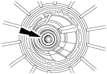
71. Install the SST.
b5r5za00000517
|
72. Measure the distance from the top of the gauge bar to the drum bearing surface through the hole in the disc and record as dimension A. Repeat the measurement 180 degrees on the opposite side of the SST and record as dimension B.
b5r5za00000518
|
73. Add dimension A to B, divide by 2 and record as dimension C.
74. Subtract the thickness of the gauge bar 17.78 mm {0.70 in} from dimension C and record as dimension D.
75. Select the thrust washer (No.1) from the following chart using dimension D.
Thrust washer (No.1) size (overdrive brake drum)
|
Dimension D |
Bearing Thickness |
Identification (Color/ID) |
|---|---|---|
|
38.05—38.13 mm {1.50 in}
|
1.55—1.60 mm {0.061—0.063 in}
|
White
|
|
38.14—38.28 mm {1.50—1.51 in}
|
1.75—1.80 mm {0.069—0.071 in}
|
Green
|
|
38.29—38.42 mm {1.51 in}
|
1.85—1.90 mm {0.073—0.075 in}
|
Red
|
|
38.43—38.61 mm {1.51—1.52 in}
|
2.05—2.10 mm {0.081-0.083 in}
|
Black
|
|
38.63—38.74 mm {1.52—1.53 in}
|
2.15—2.20 mm {0.095—0.097 in}
|
Yellow
|
76. Install the selected thrust washer (No.1).
b5r5za00000252
|
77. Install the pump gasket.
b5r5za00000254
|
78. Install the fluid pump.
b5r5za00000023
|
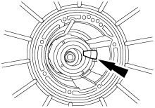
79. Install a new locknut on the band adjustment screw.
b5r5za00000259
|
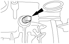
80. Tighten the intermediate brake band adjustment screw.
b5r5za00000519
|
81. Tighten the locknut.
b5r5za00000261
|
82. Install a new locknut on the band adjustment screw.
b5r5za00000262
|
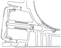
83. Tighten the overdrive brake band adjustment screw.
b5r5za00000520
|
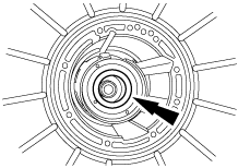
84. Tighten the locknut.
b5r5za00000264
|
85. Tighten the center support bolt.
b5r5za00000265
|
86. Install the main control valve body and loosely install the bolts.
b5r5za00000268
|
87. Tighten the bolts in the sequence shown.
b5r5za00000270
|
88. With the manual lever in the N position, install the detent spring.
b5r5za00000271
|
89. Install new O-rings on the solenoid body connector. Lubricate the O-rings with clean ATF.
b5r5za00000272
|
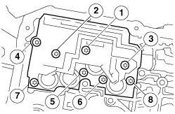
90. Install the solenoid body. Tighten bolts in the sequence shown.
b5r5za00000273
|
91. Install the reverse servo. Tighten the bolts in the sequence shown in 2 stages.
b5r5za00000274
|
92. Lubricate the seals and install the transmission fluid filter.
b5r5za00000275
|
93. Install the transmission fluid pan and gasket, magnet and loosely install the bolts.
b5r5za00000276
|
94. Tighten the bolts in a crisscross sequence.
b5r5za00000276
|
95. Install the parking pawl component and gasket.
b5r5za00000277
|
96. Install the extension housing.(4×2)
b5r5za00000278
|
97. Using the SST, install the extension housing seal.(4×2)
b5r5za00000402
|
98. Install the extension housing.(4×4)
b5r5za00000012
|
99. Using the SST, install the extension housing seal.(4×4)
absggw00001953
|
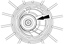
100. Install the digital TR sensor and loosely install the bolts.
b5r5za00000392
|
101. Using the SST, align the digital TR sensor and tighten the bolts in an alternating sequence.
b5r5za00000401
|
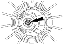
102. Install the manual shaft lever.
b5r5za00000394
|
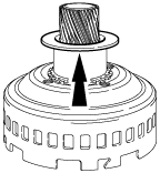
103. Install the input shaft.
b5r5za00000284
|
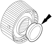
104. Lubricate the converter hub with clean ATF.
b5r5za00000286
|
105. Install the torque converter by pushing and rotating.
b5r5za00000395
|
106. Lubricate the torque converter pilot hub with multi-purpose grease.
b5r5za00000288
|
107. Using one of the sensor holes, fill the transmission with 8.5 L {9.0 US qt, 7.5 lmp qt} of ATF.
b5r5za00000291
|
108. Install the sensors.
b5r5za00000396
|