|
1
|
VERIFY RELATED SERVICE INFORMATION AVAILABILITY
• Check for related Service Information availability.
• Is any related Service Information available?
|
Yes
|
Perform repair or diagnosis according to available Service Information.
• If vehicle is not repaired, go to the next step.
|
|
No
|
Go to the next step.
|
|
2
|
• Verify stored DTC.
• Have DTCs P0115, P0134, P1110 and/or P1170 been stored?
|
Yes
|
Inspect for open or short circuit in following wiring harnesses, then go to Step 11.
• PCM terminal 2D—MAF sensor, O2S, IAT sensor, and/or ECT sensor
• Between PCM terminal 2C and engine ground
|
|
No
|
Go to the next step.
|
|
3
|
• Does TP sensor connector or PCM connector have poor connection?
|
Yes
|
Repair or replace connector, then go to Step 11.
|
|
No
|
Go to the next step.
|
|
4
|
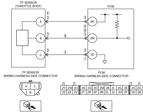
• Disconnect TP sensor connector.
• Turn the ignition switch to the ON position.
• Is there 5V at TP sensor harness side connector terminal A?
|
Yes
|
Go to the next step.
|
|
No
|
Inspect for open or short circuit in wiring harness (between PCM terminal 2K and TP sensor terminal A), then go to Step 11.
|
|
5
|
• Disconnect PCM connector.
• TP sensor is disconnected.
• Is there continuity between TP sensor harness side connector terminal C and PCM harness side connector terminal 2D?
|
Yes
|
Go to the next step.
|
|
No
|
Repair open circuit, then go to Step 11.
|
|
6
|
• Is there continuity between TP sensor harness side connector terminal B and PCM harness side connector terminal 2M?
|
Yes
|
Go to the next step.
|
|
No
|
Repair or replace wiring harness, then go to Step 11.
|
|
7
|
• Is there continuity from PCM harness side connector terminals 2D to 1B?
|
Yes
|
Repair short to power supply, then go to Step 11.
|
|
No
|
Go to the next step.
|
|
8
|
• Is there continuity from PCM harness side connector terminals 2M to 1B?
|
Yes
|
Repair short to power supply, then go to Step 11.
|
|
No
|
Go to the next step.
|
|
9
|
• Is there continuity from PCM harness side connector terminals 2M to body ground?
|
Yes
|
Repair short to ground circuit, then go to Step 11.
|
|
No
|
Go to the next step.
|
|
10
|
• Connect TP sensor and PCM connectors.
• Connect the M-MDS to the DLC-2.
• Turn the ignition switch to the ON position.
• Access TP PID.
• Does TP PID increase linear according to throttle valve opening angle?
-
Note
-
• If the M-MDS is not used, measure PCM 2M terminal voltage with circuit tester.
|
Yes
|
Go to the next step.
|
|
No
|
Verify the TP sensor, then go to the next step.
|
|
11
|
VERIFY TROUBLESHOOTING OF DTC P0120 COMPLETED
• Make sure to reconnect all disconnected connectors.
• Clear DTC from memory using the M-MDS.
• Start engine.
• Retrieve the DTCs using the M-MDS.
• Is same DTC present?
|
Yes
|
Replace PCM, then go to the next step.
|
|
No
|
Go to the next step.
|
|
12
|
VERIFY AFTER REPAIR PROCEDURE
• Perform “AFTER REPAIR PROCEDURE”.
• Is there any DTC present?
|
Yes
|
Go to applicable DTC inspection.
|
|
No
|
Troubleshooting completed.
|