 |
absggn00000320
SIMULATION TEST [G6]
id010295100600
Simulation Function
Simulation test table
|
Item |
Full name |
Condition/Unit |
Test condition |
PCM terminal |
|
|---|---|---|---|---|---|
|
IG ON |
IDLE |
||||
|
ACCS
|
A/C relay
|
On/Off
|
×
|
×
|
1J
|
|
EVAPCP
|
Purge solenoid valve duty value
|
%
|
×
|
×
|
2X
|
|
FP
|
Fuel pump relay
|
On/Off
|
×
|
×
|
1H
|
|
FPRC
|
PRC solenoid valve
|
On/Off
|
×
|
×
|
2T
|
|
FUELPW1
|
Fuel injector
|
%
|
×
|
×
|
2U, 2V
|
|
IAC
|
IAC valve control
|
ms
|
×
|
×
|
2W
|
|
INJ 1
|
Fuel injector No.1, No.3
|
OFF
|
×
|
×
|
2U
|
|
INJ 2
|
Fuel injector No.2, No.4
|
OFF
|
×
|
×
|
2V
|
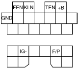
Data Link Connector (DLC)
Function
Terminal description
absggn00000320
|
|
Terminal |
Function |
Remark |
|
|---|---|---|---|
|
FEN
|
Outputs DTCs related to PCM
|
When using voltmeter
|
|
|
KLN
|
• Outputs DTCs related to PCM
• PID/DATA MONITOR AND RECORD function
• SIMULATION function
|
Mazda Modular Diagnostic System (M-MDS) communication line
|
|
|
TEN
|
Diagnostic test mode switching
|
Terminal grounded: Test mode
|
|
|
+B
|
B+
|
—
|
|
|
GND
|
Ground
|
—
|
|
|
IG–
|
Engine speed measurement
|
Connected to tachometer
|
|
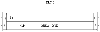
Data Link Connector-2 (DLC-2)
arnffn00000214
|
|
Terminal |
Function |
|---|---|
|
KLN
|
Serial communication KLN terminal
|
|
GND1
|
Body ground terminal
|
|
GND2
|
Serial communication ground terminal
|
|
B+
|
Battery power supply terminal
|