 |
dbg110awbr50
ON-BOARD DIAGNOSTIC TEST [WL-3]
id0102b8801000
DTCs Reading Procedure
Using M‐MDS
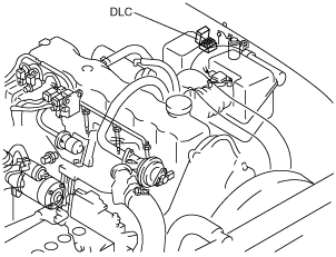
1. Connect the M-MDS to the DLC.
dbg110awbr50
|
2. After the vehicle is identified, select the following items from the initial screen of the M-MDS.
3. Then, select the “Retrieve CMDTCs” and perform procedures according to directions on the M-MDS screen.
4. Verify the DTC according to the directions on the M-MDS screen.
5. After completion of repairs, clear all DTCs stored in the PCM, while referring to “AFTER REPAIR PROCEDURE“.
Using glow indicator light
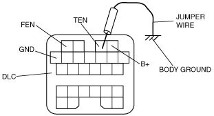
1. Turn the engine switch off.
2. Short the DLC terminal TEN to body ground using a jumper wire.
dbg110awbr50
|
dbg102awb302
|
3. Turn the engine switch to the ON position. (Engine off)
4. The glow indicator light illuminates for approx. 3 s, then goes off.
dbg102awb304
|
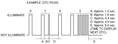
5. Read the DTCs indicated by the illumination of the glow indicator light.
Using voltmeter
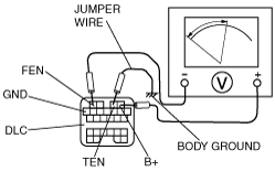
1. Turn the engine switch off.
2. Short the DLC terminal TEN to body ground using a jumper wire.
dbg110awbr50
|
dbg102awb301
|
3. Connect the negative lead of voltmeter (20 V range) to the DLC terminal FEN, and positive lead to the DLC terminal B+.
4. Turn the engine switch to the ON position. (Engine off)
5. The voltmeter indicates the battery positive voltage for approx. 3 s, then indicates 0 V.
dbg102awb303
|
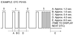
6. Read the DTCs indicated by the movement of the voltmeter’s needle.
PID/DATA Monitor and Record Procedure
1. Connect the M-MDS to the DLC.
dbg110awbr50
|
2. After the vehicle is identified, select the following items from the initial screen of the M-MDS.
3. Select the PID from the PID table.
4. Verify the PID data according to the directions on the M-MDS screen.
Simulation Function Procedure
1. Connect the M-MDS to the DLC.
dbg110awbr50
|
2. After the vehicle is identified, select the following items from the initial screen of the M-MDS.
3. Select the simulation items from the PID table.
4. Perform the simulation function, inspect the operations for each parts.