|
1
|
VERIFY RELATED REPAIR INFORMATION AVAILABILITY
• Verify related service repair information availability.
• Is any related repair information available?
|
Yes
|
Perform repair or diagnosis according to the available repair information.
• If the vehicle is not repaired, go to the next step.
|
|
No
|
Go to the next step.
|
|
2
|
VERIFY CURRENT SIGNAL STATUS: IS CONCERN INTERMITTENT OR CONSTANT?
• Start the engine.
• Is the same DTC present?
|
Yes
|
Go to the next step.
|
|
No
|
Intermittent concern exists.
Perform the “INTERMITTENT CONCERN TROUBLESHOOTING”.
|
|
3
|
VERIFY IF OTHER DTCS ARE PRESENT
• Are other DTCs present?
|
Yes
|
Perform the appropriate DTC troubleshooting procedure.
then go to Step 8.
|
|
No
|
Go to the next step.
|
|
4
|
INSPECT FUEL INJECTION PUMP CONNECTOR FOR POOR CONNECTION
• Turn the engine switch to the off position.
• Disconnect the fuel injection pump connector A.
• Check for poor connection (damaged, pulled-out pins, corrosion, etc.).
• Is there a malfunction?
|
Yes
|
Repair or replace the terminal, then go to Step 9.
|
|
No
|
Go to the next step.
|
|
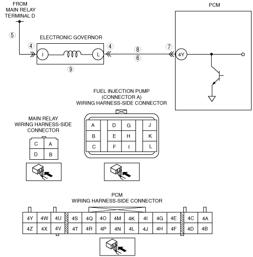
5
|
INSPECT ELECTRONIC GOVERNOR POWER CIRCUIT
• Turn the engine switch to the ON position (Engine off).
• Measure the voltage between fuel injection pump connector A terminal I (wiring harness-side) and body ground.
• Is the voltage B+?
|
Yes
|
Go to the next step.
|
|
No
|
Repair or replace the electronic governor power circuit for an open circuit, then go to Step 9.
|
|
6
|
INSPECT ELECTRONIC GOVERNOR CONTROL CIRCUIT FOR SHORT TO GROUND
• Turn the engine switch to the off position.
• Check for continuity between fuel injection pump connector A terminal L (wiring harness-side) and body ground.
• Is there continuity?
|
Yes
|
Repair or replace electronic governor control circuit for an short to ground, then go to Step 9.
|
|
No
|
Go to the next step.
|
|
7
|
INSPECT PCM CONNECTOR FOR POOR CONNECTION
• Disconnect the PCM connector.
• Check for poor connection (damaged, pulled-out pins, corrosion, etc.).
• Is there a malfunction?
|
Yes
|
Repair or replace the terminal, then go to Step 9.
|
|
No
|
Go to the next step.
|
|
8
|
INSPECT ELECTRONIC GOVERNOR CONTROL CIRCUIT FOR OPEN CIRCUIT
• Check for continuity between fuel injection pump connector A terminal L (wiring harness-side) and PCM terminal 4Y (wiring harness-side).
• Is there continuity?
|
Yes
|
Fuel injection pump may have malfunction. Consult your distributor for inspection of fuel injection pump.
Go to the next step.
|
|
No
|
Repair or replace the electronic governor control circuit for an open circuit, then go to the next step.
|
|
9
|
INSPECT ELECTRONIC GOVERNOR
• Perform the electronic governor Inspection.
• Is the electronic governor normal?
|
Yes
|
The fuel injection pump may have the mechanical malfunction. Consult your distributor for the inspection of the fuel injection pump.
Then go to the next step.
|
|
No
|
Consult your distributor for the replacement of the electronic governor.
Then go to the next step.
|
|
10
|
VERIFY TROUBLESHOOTING OF DTC P0251 COMPLETED
• Make sure to reconnect all disconnected connectors.
• Turn the engine switch to the ON position (Engine off).
• Clear the DTCs from the PCM memory using the M-MDS.
• Start the engine.
• Is the same DTC present?
|
Yes
|
Replace the PCM, then go to the next step.
|
|
No
|
Go to the next step.
|
|
11
|
VERIFY AFTER REPAIR PROCEDURE
• Perform “AFTER REPAIR PROCEDURE”.
• Is there any DTC present?
|
Yes
|
Go to applicable DTC inspection.
|
|
No
|
Troubleshooting completed.
|