|
1
|
VERIFY RELATED REPAIR INFORMATION AVAILABILITY
• Verify related service repair information availability.
• Is any related repair information available?
|
Yes
|
Perform repair or diagnosis according to the available repair information.
• If the vehicle is not repaired, go to the next step.
|
|
No
|
Go to the next step.
|
|
2
|
VERIFY CURRENT SIGNAL STATUS: IS CONCERN INTERMITTENT OR CONSTANT?
• Start the engine.
• Is the same DTC present?
|
Yes
|
Go to the next step.
|
|
No
|
Intermittent concern exists.
Perform the “INTERMITTENT CONCERN TROUBLESHOOTING”.
|
|
3
|
INSPECT EGR VALVE POSITION SENSOR CONNECTOR
• Turn the engine switch to the off position.
• Disconnect the EGR valve position sensor connector.
• Check for poor connection (damaged, pulled-out pins, corrosion, etc.).
• Are there any concerns?
|
Yes
|
Repair the terminal, then go to Step 18.
|
|
No
|
Go to the next step.
|
|
4
|
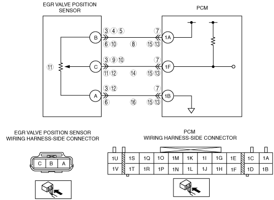
CHECK POWER SUPPLY CIRCUIT VOLTAGE AT EGR VALVE POSITION SENSOR CONNECTOR
• Turn the engine switch to the ON position (Engine off).
• Measure the voltage between EGR valve position sensor terminal B (wiring harness-side) and body ground.
• Is the voltage within 4.5— 5.5 V?
|
Yes
|
Go to Step 9.
|
|
No
|
• If the voltage is B+, repair or replace the shorted wiring harness, then go to Step 18.
• If the voltage is approx. 0 V, go to the next step.
|
|
5
|
INSPECT EGR VALVE POSITION SENSOR POWER SUPPLY CIRCUIT FOR SHORT TO GROUND
• Check for continuity between EGR valve position sensor terminal B (wiring harness-side) and body ground.
• Is there continuity?
|
Yes
|
Repair or replace the shorted wiring harness, then go to Step 18.
|
|
No
|
Go to the next step.
|
|
6
|
INSPECT EGR VALVE POSITION SENSOR POWER SUPPLY AND GROUND CIRCUIT FOR SHORT TO EACH OTHER
• Check for continuity between EGR valve position sensor terminals B (wiring harness-side) and A (wiring harness-side).
• Is there continuity?
|
Yes
|
Repair or replace the shorted wiring harness, then go to Step 18.
|
|
No
|
Go to the next step.
|
|
7
|
CHECK PCM CONNECTOR
• Disconnect the PCM connector.
• Check for poor connection at terminal 1A (damaged, pulled-out pins, corrosion, etc.).
• Is there any concern?
|
Yes
|
Repair the terminal, then go to Step 18.
|
|
No
|
Go to the next step.
|
|
8
|
VERIFY EGR VALVE POSITION SENSOR POWER SUPPLY CIRCUIT FOR OPEN CIRCUIT
• Check for continuity between EGR valve position sensor terminal B (wiring harness-side) and PCM terminal 1A (wiring harness-side).
• Is there continuity?
|
Yes
|
Go to Step 18.
|
|
No
|
Repair or replace the suspected wiring harness, then go to Step 18.
|
|
9
|
CHECK SIGNAL CIRCUIT VOLTAGE AT EGR VALVE POSITION SENSOR CONNECTOR
• Turn the engine switch to the ON position (Engine off).
• Measure the voltage between EGR valve position sensor terminal C (wiring harness-side) and body ground.
• Is the voltage within 4.5— 5.5 V?
|
Yes
|
Go to Step 15.
|
|
No
|
• If the voltage is B+, repair or replace the shorted wiring harness, then go to Step 18.
• If the voltage is approx. 0 V, go to Step 11.
|
|
10
|
INSPECT EGR VALVE POSITION SENSOR POWER SUPPLY AND SIGNAL CIRCUIT FOR SHORT TO EACH OTHER
• Check for continuity between EGR valve position sensor terminals B (wiring harness-side) and C (wiring harness-side).
• Is there continuity?
|
Yes
|
Repair or replace the shorted wiring harness, then go to Step 18.
|
|
No
|
Go to the next step.
|
|
11
|
INSPECT EGR VALVE POSITION SENSOR SIGNAL CIRCUIT FOR SHORT TO GROUND
• Check for continuity between EGR valve position sensor terminal C (wiring harness-side) and body ground.
• Is there continuity?
|
Yes
|
Repair or replace the shorted wiring harness, then go to Step 18.
|
|
No
|
Go to the next step.
|
|
12
|
INSPECT EGR VALVE POSITION SENSOR TO THE SIGNAL AND GROUND CIRCUIT FOR SHORT EACH OTHER
• Check for continuity between EGR valve position sensor terminals C (wiring harness-side) and A (wiring harness-side).
• Is there continuity?
|
Yes
|
Repair or replace the shorted wiring harness, then go to Step 18.
|
|
No
|
Go to the next step.
|
|
13
|
CHECK PCM CONNECTOR
• Disconnect the PCM connector.
• Check for poor connection at terminal 1F (damaged, pulled-out pins, corrosion, etc.).
• Is there any concern?
|
Yes
|
Repair the terminal, then go to Step 18.
|
|
No
|
Go to the next step.
|
|
14
|
VERIFY EGR VALVE POSITION SENSOR SIGNAL CIRCUIT FOR OPEN CIRCUIT
• Disconnect the PCM connector.
• Check for continuity between EGR valve position sensor terminal C (wiring harness-side) and PCM terminal 1F (wiring harness-side).
• Is there continuity?
|
Yes
|
Go to Step 18.
|
|
No
|
Repair or replace the suspected wiring harness, then go to Step 18.
|
|
15
|
CHECK PCM CONNECTOR
• Disconnect the PCM connector.
• Check for poor connection at terminal 1B (damaged, pulled-out pins, corrosion, etc.).
• Is there any concern?
|
Yes
|
Repair the terminal, then go to Step 18.
|
|
No
|
Go to the next step.
|
|
16
|
VERIFY EGR VALVE POSITION SENSOR GROUND CIRCUIT FOR OPEN CIRCUIT
• Check for continuity between EGR valve position sensor terminal A (wiring harness-side) and PCM terminal 1B (wiring harness-side).
• Is there continuity?
|
Yes
|
Go to the next step.
|
|
No
|
Repair or replace the suspected wiring harness, then go to Step 18.
|
|
17
|
INSPECT EGR VALVE POSITION SENSOR
• Perform the EGR valve position sensor inspection.
• Is the EGR position sensor normal?
|
Yes
|
Go to the next step.
|
|
No
|
Replace the EGR valve position sensor, then go to the next step.
|
|
18
|
VERIFY TROUBLESHOOTING OF DTC P1402 COMPLETED
• Make sure to reconnect all disconnected connectors.
• Start the engine.
• Clear the DTCs from the PCM memory using the M-MDS.
• Is the same DTC present?
|
Yes
|
Replace the PCM, then go to the next step.
|
|
No
|
Go to the next step.
|
|
19
|
VERIFY AFTER REPAIR PROCEDURE
• Perform “After Repair Procedure”
• Is there any DTC present?
|
Yes
|
Go to the applicable DTC inspection.
|
|
No
|
Troubleshooting completed.
|