 |
arnffw00001093
ENGINE TUNE-UP [WLT-1, WLT-2]
id011096800600
Engine Tune-up Preparation
1. Start the engine and warm up completely.
2. Verify that the gear is in neutral position.
3. Verify that the accelerator pedal is released.
4. Turn off the A/C switch. (if equipped)
5. Turn off all electrical loads.
Idle Speed Inspection
WLT-1
1. Perform “Engine Tune-up Preparation”.
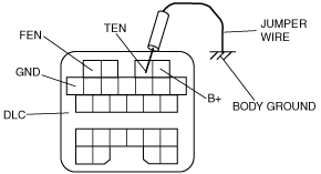
2. Use a jumper wire to short terminal TEN of the DLC to body ground.
arnffw00001093
|
3. Verify that the idle speed is within the specification.
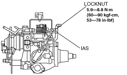
4. If not within the specification, adjust the idle speed by turning the IAS (idle adjustment screw).
absggw00000369
|
5. After adjusting the idle speed, tighten the locknut securely.
6. Disconnect a jumper wire.
WLT-2
1. Perform “Engine tune-up preparation”.
2. Use a jumper wire to short terminal TEN of the DLC to body ground.
arnffw00001093
|
3. Verify that the idle speed is within the specification.
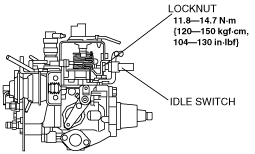
4. If not as specified, loosen the idle switch locknut and adjust the idle speed by turning the idle switch.
absggw00000370
|
5. After adjusting the idle speed, tighten the locknut securely.
6. Disconnect a jumper wire.
Idle-Up Speed Adjustment
1. Perform “Engine tune-up preparation”.
2. Use a jumper wire to short terminal TEN of the DLC to body ground.
arnffw00001093
|
3. Turn all electrical loads off in neutral shift position.
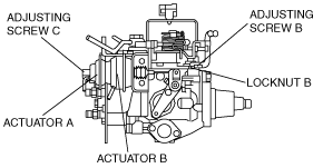
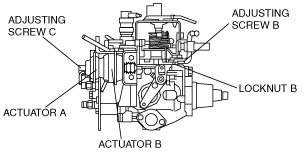
4. Apply vacuum of -53 kPa {-398 mmHg, -15.7 inHg} or over to actuator B, and measure the idle-up speed.
WLT-1
absggw00000371
|
WLT-2
absggw00000372
|
5. If not within the specification, do as follows;
6. Release actuator B to atmosphere and apply vacuum of -53 kPa {-398 mmHg, -15.7 inHg} or over to actuator A, and measure the idle-up speed.
7. If not as specified, adjust the idle-up speed by turning adjusting screw C.
8. Disconnect a jumper wire.
Injection Timing Adjustment
1. Remove the injection pipes. (See FUEL INJECTION PUMP REMOVAL/INSTALLATION [WLT-1, WLT-2].)
2. Remove the cooling fan. (See COOLING FAN REMOVAL/INSTALLATION [WLT-1, WLT-2, WL-3].)
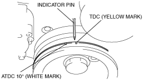
3. Turn the crankshaft pulley at slow rotation to align the timing mark (BTCD 0°: yellow mark) with indicator pin.
absggw00000236
|
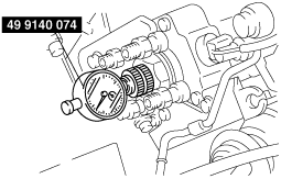
4. Remove the hydraulic head plug from the injection pump.
5. Mount the SST into the plug hole on the hydraulic plunger end of the pump and the dial indicator indicates approx. 2.0 mm {0.079 in}.
absggw00000237
|
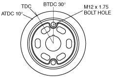
6. Turn the crankshaft counterclockwise to approx. 30 ° BTDC. (Align the SST installation hole on the crankshaft pulley.)
absggw00000238
|
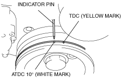
7. Turn the crankshaft lightly right and left, and verify that the dial gauge indicator does not move. Then set the indicator to 0 mm {0 in}.
8. Turn the crankshaft clockwise to position the indicator pin 10°ATDC mark (white mark) and read the dial indicator.
absggw00000239
|
9. If it is not as specified, adjust by loosening the FIP mounting nut and bolt and turn the FIP.
10. Tighten the FIP mounting nuts and then the bolt.
absggw00000373
|
11. Remove the SST.
12. Install the hydraulic head plug and a new gasket.
13. Connect the injection pipes. (See FUEL INJECTION PUMP REMOVAL/INSTALLATION [WLT-1, WLT-2].)
14. Bleed the air from the fuel filter. (See AFTER REPAIR PROCEDURE [WLT-1, WLT-2].)
15. Inspect for fuel leakage.
16. Check the timing belt tension. (See TIMING BELT REMOVAL/INSTALLATION [WLT-1, WLT-2].)