 |
absggw00000360
ROCKER ARM REMOVAL/INSTALLATION [WLT-1, WLT-2]
id011096804600
1. Disconnect the negative battery cable.
2. Remove the air intake pipe and breather chamber.
3. Remove the timing belt.
4. Remove the order indicated in the table.
5. Install in the reverse order of removal.
absggw00000360
|
|
1
|
Cylinder head cover
|
|
2
|
Camshaft pulley
(See Camshaft Pulley Removal Note.)
|
|
3
|
Seal plate
(See Seal plate Installation Note.)
|
|
4
|
Camshaft
(See Camshaft Removal Note.)
(See Camshaft Installation Note.)
|
|
5
|
Rocker arm
(See Rocker Arm Installation Note.)
|
|
6
|
Pivot
|
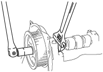
Camshaft Pulley Removal Note
1. Hold the camshaft using a wrench on the cast hexagon.
absggw00000361
|
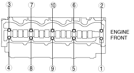
Camshaft Removal Note
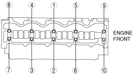
1. Loosen the camshaft cap bolts in three or four steps in the order shown.
absggw00000362
|
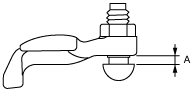
Rocker Arm Installation Note
1. If a new rocker arm is used, set dimension A as follows.
absggw00000363
|
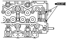
Camshaft Installation Note
1. Apply silicone sealant to the front camshaft cap mounting surfaces as indicated in the figure. Avoid getting sealant onto the camshaft journal, camshaft oil seal surface, and camshaft thrust surface.
absggw00000364
|
2. Tighten the camshaft cap bolts gradually in three or four steps in the order shown.
absggw00000365
|
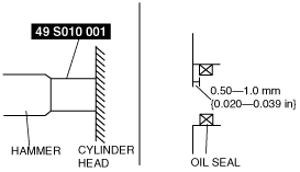
3. Apply soapy water along the perimeter of the new oil seal.
4. Push the oil seal slightly in by hand.
5. Tap the oil seal into the cylinder head using the SST and the a hammer.
absggw00000366
|
6. To ensure that the oil seal is installed correctly, measure the distance between the end of the cylinder head and the face of the oil seal.
Seal plate Installation Note
1. Tighten the seal plate bolts in the order shown.
absggw00000367
|
Camshaft Pulley Installation Note
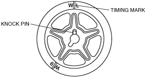
1. Install the camshaft pulley on the camshaft with the knock pin fitted into the hole at the timing mark.
absggw00000368
|
2. Hold the camshaft by using a wrench on the cast hexagon and tighten the pulley lock bolt.
absggw00000361
|