FUEL INJECTOR INSPECTION [F2]
id011494800700
Simulation Test
1. Carry out the “Fuel Injector Operation Inspection”. (See ENGINE CONTROL SYSTEM OPERATION INSPECTION [F2].)
-
• If not as specified, perform the further inspection for the fuel injectors.
Resistance Inspection
-
Note
-
• Perform the following test only when directed.
1. Disconnect the negative battery cable.
2. Disconnect the fuel injector connectors.
3. Measure the resistance of the fuel injector.
-
• If as specified but “Simulation Test” is failed, inspect for the following:
-
Fuel injector resistance
-
13.5—14.1 ohms [20 °C {68 °F}]
Open circuit
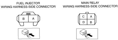
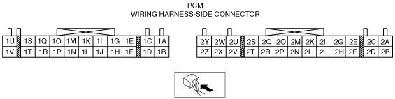
• GND circuit (No.1 cylinder fuel injector connector terminal B and PCM connector terminal 2U)
• GND circuit (No.2 cylinder fuel injector connector terminal B and PCM connector terminal 2V)
• GND circuit (No.3 cylinder fuel injector connector terminal B and PCM connector terminal 2U)
• GND circuit (No.4 cylinder fuel injector connector terminal B and PCM connector terminal 2V)
• Power circuit (No.1 cylinder fuel injector connector terminal A and main relay connector terminal D through common connector)
• Power circuit (No.2 cylinder fuel injector connector terminal A and main relay connector terminal D through common connector)
• Power circuit (No.3 cylinder fuel injector connector terminal A and main relay connector terminal D through common connector)
• Power circuit (No.4 cylinder fuel injector connector terminal A and main relay connector terminal D through common connector)
Short circuit
• No.1 cylinder fuel injector connector terminal B and PCM connector terminal 2U to GND
• No.2 cylinder fuel injector connector terminal B and PCM connector terminal 2V to GND
• No.3 cylinder fuel injector connector terminal B and PCM connector terminal 2U to GND
• No.4 cylinder fuel injector connector terminal B and PCM connector terminal 2V to GND
4. Repair or replace faulty areas.
5. Reconnect the fuel injector connectors.
6. Reconnect the negative battery cable.
Fuel Leakage Test
-
Warning
-
• Fuel line spills and leakage are dangerous. Fuel can ignite and cause serious injuries or death and damage. Always carry out the following procedure with the engine stopped.
-
Note
-
• Perform the following test only when directed.
1. Complete the “BEFORE REPAIR ROCEDURE”. (See BEFORE REPAIR PROCEDURE [F2].)
2. Disconnect the negative battery cable.
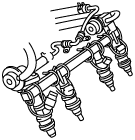
3. Remove the fuel injectors together with the fuel distributor. (See FUEL INJECTOR REMOVAL/INSTALLATION [F2].)
4. Fasten the fuel injectors firmly to the fuel distributor with wire.
5. Start the fuel pump using the following procedure:
-
Using M-MDS
-
1. Connect the negative battery cable.
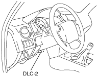
2. Connect the M-MDS to the DLC-2.
3. Start the fuel pump using the “FP” simulation function.
-
Caution
-
• Connecting the wrong DLC terminal may possibly cause a malfunction. Carefully connect the specified terminal only.
-
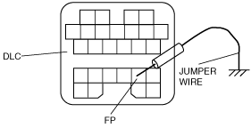
Not using M-MDS
-
1. Short the DLC terminal F/P to body ground using a jumper wire.
2. Connect the negative battery cable.
3. Turn the ignition switch to the ON position, to operate the fuel pump.
6. Tilt the fuel injectors approx. 60 ° and verify that fuel leakage from the fuel injector nozzles is within the specification.
-
• If not as specified, replace the fuel injector.
-
Fuel leakage
-
Less than 1 drop/2 min
7. Stop the fuel pump using the following procedure:
-
Using M-MDS
-
1. Stop the fuel pump using the “FP” simulation function.
-
Not using M-MDS
-
1. Turn the ignition switch to off to stop the fuel pump.
8. Complete the “AFTER REPAIR PROCEDURE”. (See AFTER REPAIR PROCEDURE [F2].)
Volume Test
-
Warning
-
• Fuel line spills and leakage are dangerous. Fuel can ignite and cause serious injuries or death and damage. Always carry out the following procedure with the engine stopped.
-
Note
-
• Perform the following test only when directed.
1. Complete the “BEFORE REPAIR PROCEDURE”. (See BEFORE REPAIR PROCEDURE [F2].)
2. Disconnect the negative battery cable.
3. Remove the fuel injectors together with the fuel distributor. (See FUEL INJECTOR REMOVAL/INSTALLATION [F2].)
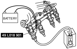
4. Fasten the fuel injectors firmly to the fuel distributor with wire.
5. Connect the SST as shown in the figure.
6. Start the fuel pump using the following procedure:
-
Using M-MDS
-
1. Connect the negative battery cable.
2. Connect the M-MDS to the DLC-2.
3. Start the fuel pump using the “FP” simulation function.
-
Caution
-
• Connecting the wrong DLC terminal may possibly cause a malfunction. Carefully connect the specified terminal only.
-
Not using M-MDS
-
1. Short the DLC terminal F/P to body ground using a jumper wire.
2. Connect the negative battery cable.
3. Turn the ignition switch to the ON position, to operate the fuel pump.
7. Measure the injection volume of each fuel injector using a graduated container.
-
• If not as specified, replace the fuel injector.
-
Injection volume
-
204—216 ml {204—216 cc, 6.9—7.3 fl oz}/min
8. Stop the fuel pump using the following procedure:
-
Using M-MDS
-
1. Stop the fuel pump using the “FP” simulation function.
-
Not using M-MDS
-
1. Turn the ignition switch to off to stop the fuel pump.
9. Complete the “AFTER REPAIR PROCEDURE”. (See AFTER REPAIR PROCEDURE [F2].)