 |
arnffw00000662
GENERATOR INSPECTION [F2]
id011794800300
Generator Warning Light
1. Verify that the battery is fully charged.
2. Verify that the drive belt deflection/tension is within the specification. (See DRIVE BELT INSPECTION [F2].)
3. Turn the ignition switch on and verify that the generator warning light illuminates.
4. Verify that the generator warning light goes out after the engine is started.
Generator
Voltage
1. Verify that the battery is fully charged.
2. Verify that the drive belt deflection/tension is within the specification. (See DRIVE BELT INSPECTION [F2].)
3. Turn off all electrical loads.
4. Turn the ignition switch to start the engine and verify that the generator rotates smoothly without any noise while the engine is running.
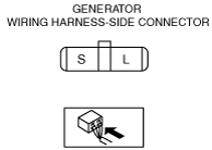
5. Measure the voltage at each terminal using a tester.
arnffw00000662
|
Current
1. Verify that the battery is fully charged.
2. Verify that the drive belt deflection/tension is within the specification. (See DRIVE BELT INSPECTION [F2].)
3. Disconnect the negative battery cable.
4. Connect a tester, which can read 120 A or more, between generator terminal B and the wiring harness.
5. Turn off all electrical loads.
6. Start the engine and increase the engine speed to 2,000—2,500 rpm.
7. Turn the following electrical loads on and verify that the current reading increases.
Generator generated current (reference value) [Conditions] Ambient temperature: 20 °C {68 °F}, Voltage: 13.5 V, Engine hot
|
Engine speed (rpm) |
Terminal B current (Lower limit of current must be more than 0 A.) |
|
|---|---|---|
|
1,000
|
0—43 A
|
|
|
2,000
|
0—62 A
|
|
Generator Inner Parts
Rotor
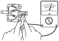
1. Measure the resistance between the slip rings using a tester.
arnffw00000663
|
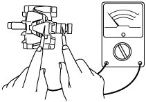
2. Verify that there is no continuity between the slip ring and core using a tester.
arnffw00000664
|
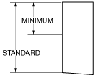
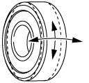
3. Inspect the slip ring surface condition.
Stator coil
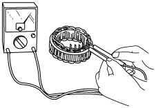
1. Inspect for continuity between the stator coil leads using a tester.
arnffw00000665
|
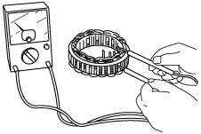
2. Verify that there is no continuity between the stator coil leads and the core using a tester.
arnffw00000666
|
Brush
1. Inspect brushes for wear.
arnffw00000667
|
Brush spring
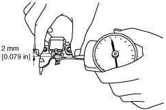
1. Measure the force of the brush spring using a spring pressure gauge.
2. Read the spring pressure gauge at the brush tip projection of 2 mm {0.079 in}.
arnffw00000668
|
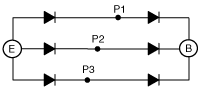
Rectifier (Using an analog circuit tester)
1. Inspect for continuity of the diodes using an analog circuit tester.
arnffw00000669
|
arnffw00000670
|
Specification
|
Tester |
Continuity |
|
|---|---|---|
|
Negative |
Positive |
|
|
E
|
P1, P2, P3
|
Yes
|
|
B
|
No
|
|
|
P1, P2, P3
|
E
|
No
|
|
B
|
Yes
|
|
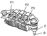
Rectifier (Using a digital circuit tester)
1. Inspect for continuity of the diodes using a digital circuit tester.
Specification
|
Tester |
Continuity |
|
|---|---|---|
|
Negative |
Positive |
|
|
E
|
P1, P2, P3
|
No
|
|
B
|
Yes
|
|
|
P1, P2, P3
|
E
|
Yes
|
|
B
|
No
|
|
Bearing
1. Inspect for abnormal noise, looseness, and sticking.
arnffw00000671
|