 |
acxuuw00002040
STARTER INSPECTION [F2]
id011994800300
On-vehicle Inspection
1. Verify that the battery is fully charged.
2. The starter is normal if it rotates smoothly and without any noise when the engine is cranked.
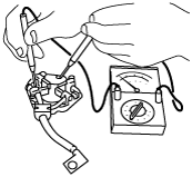
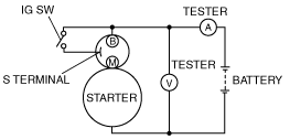
No-load test
1. Verify that the battery is fully charged.
2. Connect the starter, battery, and a tester as shown in the figure.
acxuuw00002040
|
3. Operate the starter and verify that it rotates smoothly.
4. Measure the voltage and current while the starter is operating.
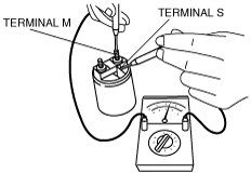
Magnetic Switch Operation Inspection
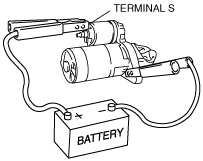
Pull‐out test
1. Verify that the starter motor pinion is protracted while battery positive voltage is connected to terminal S and the starter body is grounded.
arnffw00000708
|
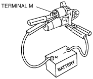
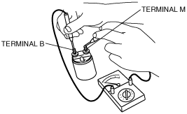
Return test
1. Disconnect the motor wire from terminal M.
2. Connect battery positive voltage to terminal M and ground the starter body.
arnffw00000709
|
3. Pull out the drive pinion with a screwdriver. Verify that it returns to its original position when released.
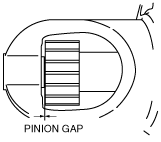
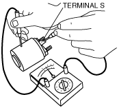
Pinion Gap Inspection
1. Pull out the drive pinion with the battery positive voltage connected to terminal S and the starter body grounded.
arnffw00000708
|
2. Measure the pinion gap while the drive pinion is pulled.
arnffw00000710
|
Starter Inner Parts Inspection
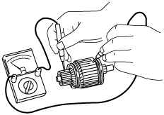
Armature
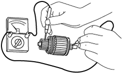
1. Verify that there is no conductivity between the commutator and the core at each segment using a tester.
arnffw00000711
|
2. Verify that there is no conductivity between the commutator and the shaft using a tester.
arnffw00000712
|
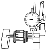
3. Place the armature on V‐blocks, and measure the runout using a dial indicator.
arnffw00000713
|
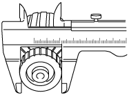
4. Measure the commutator diameter.
arnffw00000714
|
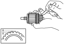
5. Measure the segment groove depth of the commutator.
arnffw00000715
|
Magnetic switch
1. Inspect for conductivity between terminals S and M using a tester.
arnffw00000716
|
2. Inspect for conductivity between terminal S and the body using a tester.
arnffw00000717
|
3. Verify that there is no conductivity between terminals M and B using a tester.
arnffw00000718
|
Brush and brush holder
1. Verify that there is no conductivity between each insulated brush and plate using a tester.
arnffw00000719
|
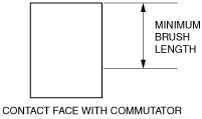
2. Measure the brush length.
arnffw00000720
|
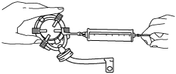
3. Measure the brush spring force using a spring balance.
arnffw00000721
|