ELECTRONIC SPARK ADVANCE (ESA) CONTROL OPERATION [G6]
id014095179500
Ignition Timing
Control outline
-
• The PCM controls the ignition timing to either fixed ignition or cycle estimated ignition according to the engine operation conditions.
Fixed ignition
• The final ignition timing is fixed at the SGT signal trailing edge (BTDC 5 ° or 6 ° CA)
Cycle estimation ignition
• To obtain the optimum ignition timing, the PCM determines the final ignition timing by estimating the next ignition timing according to the engine conditions.
Energized Time
Control outline
-
• The PCM controls the energization time of the ignition coil according to the estimated final ignition timing and the engine conditions.
Igniter energization time
• During fixed ignition, energization starts with the SGT signal trailing edge.
• During cycle estimation ignition, energization starts at the time estimated by SGT signal cycle and engine operation conditions (constant speed driving, acceleration, deceleration) and is cut at the estimated final ignition timing.
• When the energization time exceeds the predetermined period, energization is automatically cut to prevent damage to the transistor caused by the continuous energization to the ignition coil.
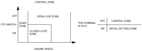
Control Zones
Control outline
-
• To obtain the optimum ignition timing control, the PCM divides the ignition timing control into four zones and calculates the final ignition timing according to the engine conditions.
Start zone
• The start zone corresponds to the cranking time when engine speed is below 500 rpm.
• In start zone, fixed ignition is applied (BTDC 6 ° CA). Although, during ECT 80—105 °C {176—221 °F} with IAT 30—80 °C {86—176 °F}, fixed ignition is applied (BTDC -2.3—4.3 ° CA) when engine speed is below 500 rpm.
Initial setting zone
• The control is in initial setting zone when DLC terminal TEN is grounded.
• In the initial setting zone, fixed ignition is applied (BTDC 5 ° CA)
Idle zone
• In the idle zone, cycle estimated ignition is applied.
• The idle zone is when idling under no load condition.
• The ignition timing for the idle zone is calculated using the following formula:
Ignition timing = Idle spark advance + Closed loop correction
• The idle spark advance is determined according to the ECT and stability when idling has been improved. The lower the ECT is, the larger the spark advance value becomes.
Normal driving zone
• In the normal driving zone, cycle estimated ignition is applied.
• The control is in the normal driving zone when it is in other than the above zones.
• The ignition timing for the idle zone is calculated using the following formula:
Ignition timing = Basic spark advance - Acceleration spark retard correction +
IAT spark retard correction + ECT spark advance correction
• The basic spark advance is determined according to engine speed and charging efficiency to set spark advance characteristics suitable for the engine. The higher the engine speed is and the lower the charging efficiency is, the larger the basic spark advance value becomes.
|
Correction
|
Purpose
|
Conditions
|
Action
|
|
Closed loop correction
|
To maintain idle speed stability
|
When difference between idle speed and target speed exceeds specified value
|
Present speed > target speed → Larger spark retard
Present speed < target speed → Larger spark advance
|
|
ECT spark advance correction
|
To maintain engine speed stability when engine cold
|
When engine cold, according to ECT
|
Lower ECT → Larger spark advance
|
|
IAT spark retard correction
|
To prevent knocking when IAT high
|
Depends on IAT.
|
High IAT → Larger spark retard.
|
|
Acceleration spark retard correction
|
To prevent knocking during sudden acceleration
|
When sudden acceleration detected
|
During sudden acceleration → Spark retard
|