 |
arnffw00001190
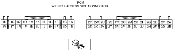
PCM INSPECTION [G6]
id014095802500
Using M-MDS
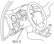
1. Connect the M-MDS to the DLC-2.
arnffw00001190
|
2. Turn the ignition switch to ON position.
3. Measure the PID value.
PID MONITOR Table
|
Monitor item (Definition) |
Unit/Condition |
Condition/Specification (Reference) |
Inspection item (s) |
PCM terminal |
|
|---|---|---|---|---|---|
|
ACCS
(A/C relay)
|
On/Off
|
• Ignition switch on:Off
• A/C switch on and fan switch on at idle:On
|
• The following PIDs
• A/C relay
|
1J
|
|
|
ACSW
(A/C switch)
|
On/Off
|
• A/C switch and fan switch on at ignition switch on: On
• A/C switch off at ignition switch on: Off
|
• A/C switch
|
1Q
|
|
|
ARPMDES
(Target engine speed)
|
RPM
|
• Indicate the target engine speed
|
• CMP sensor
|
—
|
|
|
BARO
(Barometric pressure)
|
Kpa
|
• Below 400 m {0.25 mile} above sea level:100—103kPa {1.01—10.5 kgf/cm2}
|
• DTCP1195 is indicated.
follow DTC Troubleshooting
|
—
|
|
|
V
|
• Below 400 m {0.25 mile} above sea level:3.9—4.0V
|
||||
|
BOO
(Brake switch)
|
On/Off
|
• Brake pedal depressed:On
• Brake pedal released:Off
|
• Brake switch
|
1O
|
|
|
CPP/PNP
(Shift lever position)
|
Drive/Neutral
|
• Neutral:Neutral
• Other than neutral:Drive
|
• Neutral switch
|
1V
|
|
|
ECT
(Engine coolant temperature)
|
°C
|
°F
|
• Indicate the ECT
|
• ECT sensor
|
2Q
|
|
V
|
• Ignition switch to the ON position (after warm up):0.58 V
|
||||
|
EVAPCP
(Purge solenoid valve duty value)
|
%
|
• Ignition swich on:0%
• Idle:0%
|
• The following PIDs
|
2X
|
|
|
FP
(Fuel pump relay)
|
On/Off
|
• Ignition swich on:Off
• Idle:On
• Cranking:On
|
• The following PIDs
• Fuel pump relay
|
1H
|
|
|
FPRC
(PRC solenoid valve)
|
On/Off
|
• Ignition swich on:Off
• Idle:Off
• Engine start at hot condition:On
|
• The following PIDs
• PRC solenoid valve
|
2T
|
|
|
FUELPW1
(Fuel injector)
|
ms
|
• Ignition switch on:0.0ms
• Idle:3.0—5.0ms
|
• The following PIDs
• CMP sensor
|
2U, 2V
|
|
|
IAC
(IAC valve control)
|
ms
|
• Idle:2.4—2.7ms
|
• The following PIDs
• IAC valve
|
2W
|
|
|
IAT
(Intake air temperature)
|
°C
|
°F
|
• Indicate the IAT
|
• IAT sensor
|
2L
|
|
V
|
• IAT 20 °C {68 °F}:2.15 V
|
||||
|
IDLE_SW
(Idle switch)
|
Idle/Off Idle
|
• Accelerator depressed:Off idle
• Accelerator released:Idle
|
• Idle switch
|
1N
|
|
|
LOAD
(Engine load)
|
%
|
• Indicate the engine load
|
—
|
—
|
|
|
LONGFT1
(Long term fuel trim)
|
%
|
• Indicate the long term fuel trim
|
—
|
—
|
|
|
MAF
(Mass air flow)
|
g/s
|
• Indicate the MAF amount
|
• MAF sensor
|
2O
|
|
|
V
|
• Ignition switch to the ON position:1.45 V
• Idle (after warm up):2.15 V
|
||||
|
MIL
(Malfunction indicator)
|
On/Off
|
• Indicate that the engine control system malfunction accurs
|
Perform applicable DTC troubleshooting
|
—
|
|
|
MTSW
(Transmission distinction)
|
1/0
|
• Ignition switch to the ON position:1
|
• Related wiring harness
|
1L
|
|
|
O2S11
(O2S)
|
V
|
• Ignition switch on:0—1.0V
• Idle (After warm up):0—1.0V
• Acceleration (After warm up):0.5—1.0V
• Deceleration (After warm up):0—0.5V
|
• O2S
|
2N
|
|
|
PSP
(PSP switch)
|
High/Low
|
• Steering wheel fully turned:High
• Steering wheel straight ahead position:Low
|
• PSP switch
|
1P
|
|
|
RPM
(Engine speed)
|
RPM
|
• Indicate engine speed
|
• CMP sensor
|
—
|
|
|
SELTESTDTC
(Diagnostic trouble codes)
|
—
|
—
|
Perform applicable DTC troubleshooting
|
—
|
|
|
SHRTFT1
(Short term fuel trim)
|
%
|
• Indicate the short term fuel trim
|
—
|
—
|
|
|
SPARKADV
(Ignition timing)
|
°
|
• Indicate the ignition timing
|
• The following PIDs
• CMP sensor
• Idle speed and ignition timing
|
2E
|
|
|
Test
(Test mode)
|
ON/OFF
|
• Test mode On:ON
• Test mode Off:OFF
|
—
|
—
|
|
|
TP
(TP sensor)
|
V
|
• Closed throttle position:0.4—0.6 V
• Wide open throttle:3.4—4.7 V
|
• TP sensor
|
2M
|
|
|
VPWR
(Battery positive voltage)
|
V
|
• Under any condition:B+
|
• Battery
|
1A
|
|
|
VSS
(Vehicle speed)
|
KPH
|
• Vehicle speed 20 km/h {mph}:20 km/h {mph}
• Vehicle speed 40 km/h {mph}:40 km/h {mph}
|
• VSS
|
1M
|
|
Without Using the M-MDS
1. Remove the PCM.
2. Reconnect PCM connector and battery negative terminal.
3. Measure the voltage at each terminal.
Terminal voltage table (Reference)
absggw00000828
|
|
Terminal |
Signal |
Connected to |
Test condition |
Voltage (V) |
Inspection item |
|
|---|---|---|---|---|---|---|
|
1A
|
Back-up power supply
|
Battery
|
Under any condition
|
B+
|
• Battery
• Related wiring harness
|
|
|
1B
|
Power supply
|
Main relay
|
Ignition switch off
|
1.0 or less
|
• Related wiring harness
|
|
|
Ignition switch to the ON position
|
B+
|
|||||
|
1C
|
—
|
—
|
—
|
—
|
—
|
|
|
1D
|
Serial communication
|
DLC (Terminal KLN)
|
Because of this terminal is for serial communication, good/no good judgment by terminal voltage is not possible. Carry out inspection according to DTCs.
|
—
|
—
|
|
|
1E
|
DTC output
|
DLC (Terminal FEN)
|
Ignition switch to the ON position and terminal TEN (in DLC) short to chassis ground
|
Not DTC stored
|
1.0 or less
|
• Related wiring harness
|
|
DTC stored
|
0—B+
|
|||||
|
DLC-2 (Terminal KLN)
|
Because of this terminal is for serial communication, good/no good judgment by terminal voltage is not possible. Carry out inspection according to DTCs.
|
—
|
—
|
|||
|
1F
|
—
|
—
|
—
|
—
|
—
|
|
|
1G
|
—
|
—
|
—
|
—
|
—
|
|
|
1H
|
Fuel pump control
|
Fuel pump relay
|
Ignition switch to the ON position
|
B+
|
• Fuel pump relay
• Related wiring harness
|
|
|
Cranking
|
1.0 or less
|
|||||
|
Idle
|
||||||
|
1I
|
—
|
—
|
—
|
—
|
—
|
|
|
1J
|
A/C control
|
A/C relay
|
A/C not operating
|
B+
|
• A/C relay
• Related wiring harness
|
|
|
A/C operating
|
1.0 or less
|
|||||
|
1K
|
Diagnostic test mode
|
DLC (Terminal TEN)
|
Ignition switch to the ON position
|
Terminal TEN (DLC) open
|
B+
|
• Related wiring harness
|
|
Terminal TEN (DLC) short to ground
|
1.0 or less
|
|||||
|
1L
|
Transmission distinction
|
Ground
|
Under any condition
|
1.0 or less
|
• Related wiring harness
|
|
|
1M
|
Vehicle speed
|
VSS
|
Vehicle stopped
|
0 or Approx. 5.0
|
• VSS
• Related wiring harness
|
|
|
Vehicle running
|
Approx. 5.0
|
|||||
|
1N
|
CTP
|
CTP switch
|
Ignition switch to the ON position
|
Accelerator pedal depressed
|
B+
|
• CTP switch
• Related wiring harness
|
|
Accelerator pedal released
|
1.0 or less
|
|||||
|
1O
|
Brake
|
Brake switch
|
Brake pedal depressed
|
B+
|
• Brake switch
• Related wiring harness
|
|
|
Brake pedal released
|
1.0 or less
|
|||||
|
1P
|
PSP
|
PSP switch
|
Idle
|
Steering wheel at straight ahead position
|
B+
|
• PSP switch
• Related wiring harness
|
|
While turning steering wheel
|
1.0 or less
|
|||||
|
1Q
|
A/C
|
A/C switch
|
Ignition switch to the ON position
|
A/C switch and fan switch on
|
1.0 or less
|
• A/C switch
• Related wiring harness
|
|
A/C switch off
|
B+
|
|||||
|
1R
|
4×2/4×4 distinction*1
|
Ground
|
Under any condition
|
1.0 or less
|
• Related wiring harness
|
|
|
1S
|
—
|
—
|
—
|
—
|
—
|
|
|
1T
|
—
|
—
|
—
|
—
|
—
|
|
|
1U
|
—
|
—
|
—
|
—
|
—
|
|
|
1V
|
Load/no load distinction
|
Neutral/clutch switch
|
Ignition switch to the ON position
|
Transmission neutral position or clutch pedal depressed
|
1.0 or less
|
• Neutral switch
• Clutch switch
• Related wiring harness
|
|
Other than transmission neutral and clutch pedal released
|
B+
|
|||||
|
2A
|
Fuel injector ground
|
Ground
|
Under any condition
|
1.0 or less
|
• Related wiring harness
|
|
|
2B
|
Power ground
|
Ground
|
Under any condition
|
1.0 or less
|
• Related wiring harness
|
|
|
2C
|
System ground
|
Ground
|
Under any condition
|
1.0 or less
|
• Related wiring harness
|
|
|
2D
|
Internal ground
|
MAF sensor, IAT sensor, ECT sensor, O2S, TP sensor
|
Under any condition
|
1.0 or less
|
• Related wiring harness
|
|
|
2E
|
CMP
|
CMP sensor (integrated into distributor)
|
Ignition switch to the ON position
|
5.0
|
• CMP sensor
• Related wiring harness
|
|
|
Idle
|
1.8—2.3
|
|||||
|
2F
|
IGT control
|
Igniter
|
Ignition switch to the ON position
|
1.0 or less
|
• Ignition control module
• Related wiring harness Related wiring harness
|
|
|
Idle
|
0.35—0.5
|
|||||
|
2G
|
—
|
—
|
—
|
—
|
—
|
|
|
2H
|
—
|
—
|
—
|
—
|
—
|
|
|
2I
|
—
|
—
|
—
|
—
|
—
|
|
|
2J
|
—
|
—
|
—
|
—
|
—
|
|
|
2K
|
Constant voltage (Vref)
|
TP sensor
|
Ignition switch to the ON position
|
4.5—5.5
|
• Related wiring harness
|
|
|
2L
|
IAT
|
IAT sensor
|
Ignition switch to the ON position
|
IAT 20 °C {68 °F}
|
2.15
|
• IAT sensor
• Related wiring harness
|
|
2M
|
TP
|
TP sensor
|
Ignition switch to the ON position
|
APP is released
|
0.4—0.6
|
• TP sensor
• Related wiring harness
|
|
APP is depressed
|
3.4—4.7
|
|||||
|
2N
|
O2S
|
O2S
|
Ignition switch to the ON position
|
0.55
|
• O2S
• Related wiring harness
|
|
|
Idle
|
Engine cold
|
0.0—1.0
|
||||
|
After warm up
|
0.0—1.0
|
|||||
|
Acceleration
|
0.5—1.0
|
|||||
|
Deceleration
|
0.0—0.5
|
|||||
|
2O
|
MAF
|
MAF sensor
|
Ignition switch to the ON position
|
1.45
|
• MAF sensor
• Related wiring harness
|
|
|
Idle (after warm up)
|
2.15
|
|||||
|
2P
|
—
|
—
|
—
|
—
|
—
|
|
|
2Q
|
ECT
|
ECT sensor
|
Ignition switch to the ON position
|
IAT 20 °C {68 °F}
|
1.02
|
• ECT sensor
• Related wiring harness
|
|
After warm up
|
0.58
|
|||||
|
2R
|
—
|
—
|
—
|
—
|
—
|
|
|
2S
|
—
|
—
|
—
|
—
|
—
|
|
|
2T
|
Pressure regulator control
|
PRC solenoid valve
|
Idle (after warm up)
|
B+
|
• PRC solenoid valve
• Related wiring harness
|
|
|
2U
|
Fuel injector control
|
Fuel injector No.1, No.3
|
Ignition switch to the ON position
|
B+
|
• Fuel injector
• Related wiring harness
|
|
|
Idle
|
B+
|
|||||
|
2V
|
Fuel injector No.2, No.4
|
Ignition switch to the ON position
|
B+
|
• Fuel injector
• Related wiring harness
|
||
|
Idle
|
B+
|
|||||
|
2W
|
IAC
|
IAC valve
|
Ignition switch to the ON position
|
0.2
|
• IAC valve
• Related wiring harness
|
|
|
Idle (after warm up)
|
Approx. 1.0
|
|||||
|
2X
|
Purge control
|
Purge solenoid valve
|
Ignition switch to the ON position
|
B+
|
• Purge solenoid valve
• Related wiring harness
|
|
|
Idle
|
B+
|
|||||
|
2Y
|
—
|
—
|
—
|
—
|
—
|
|
|
2Z
|
Engine speed output
|
Tachometer (integrated into instrument cluster)
|
Ignition switch to the ON position
|
B+
|
• Instrument cluster
• Related wiring harness
|
|
|
Idle
|
4.9—7.0
|
|||||