 |
absggw00000692
FRONT WHEEL ALIGNMENT [4x2]
id0211008002a2
Front wheel alignment [4x2] (Unloaded)
|
Item |
Specifications |
|||||
|---|---|---|---|---|---|---|
|
Regular cab, Freestyle cab |
Double cab |
High clearance model (Regular cab and Freestyle cab) |
High clearance model (Double cab) |
|||
|
Total toe-in
|
Tire
[Tolerance
±3 {0.12}]
|
(mm {in})
|
5 {0.19}
|
6 {0.23}
|
||
|
|
degree
|
0°25′±15′
|
0°28′±14′
|
|||
|
Maximum steering angle
|
Inner
|
33°00′—37°00′
|
31°30′—35°30′
|
|||
|
Outer
|
30°00′—35°00′
|
27°00′—32°00′
|
||||
|
Camber angle (reference value)
[Tolerance ±1°]
|
0°35′
|
0°44′
|
0°45′
|
|||
|
Caster angle (reference value)
[Tolerance ±1°]
|
1°56′
|
1°54′
|
2°07′
|
2°06′
|
||
|
Steering axis inclination
(reference value)
|
8°25′
|
10°37′
|
10°35′
|
|||
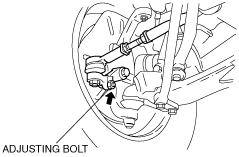
Maximum Steering Angle Adjustment
1. Loosen the adjusting bolt locknut.
2. Turn the adjusting bolt to provide the correct turning angle.
absggw00000692
|
3. After adjustment, tighten the locknut to the specified torque.
4. After adjusting the steering angle, always inspect and adjust the toe angle. (See Total Toe-in Adjustment.)
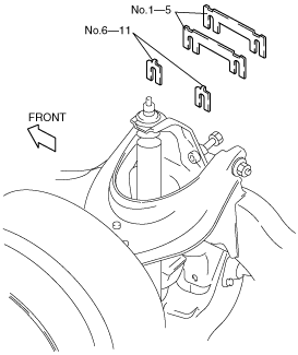
Caster And Camber Adjustment
1. Loosen the upper arm shaft bolt and insert or remove adjustment shims to provide the correct angle.
absggw00000693
|
|
No. |
Thickness (mm {in}) |
|---|---|
|
1
|
1.0 {0.039}
|
|
2
|
1.6 {0.063}
|
|
3
|
2.0 {0.079}
|
|
4
|
3.2 {0.126}
|
|
5
|
4.0 {0.157}
|
|
6
|
0.6 {0.024}
|
|
7
|
1.0 {0.039}
|
|
8
|
1.6 {0.063}
|
|
9
|
2.0 {0.079}
|
|
10
|
3.2 {0.126}
|
|
11
|
4.0 {0.157}
|
|
Shim thickness |
Variation/1 mm {0.039 in} |
|---|---|
|
Add
|
Negative 15′
|
|
Reduce
|
Positive 15′
|
|
|
Shim thickness |
Variation/1 mm {0.039 in} |
|---|---|---|
|
Front side
|
Add
|
Increase 30′
|
|
Reduce
|
Decrease 30′
|
|
|
Rear side
|
Add
|
Decrease 30′
|
|
Reduce
|
Increase 30′
|
2. After adjustment, tighten the upper arm shaft bolt to the specified torque.
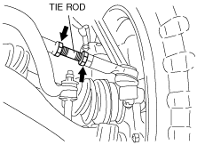
Total Toe-in Adjustment
1. Loosen the locknut of the tie-rod end.
2. Turn the tie rods by the same amount in the opposite direction.
3. Tighten the tie-rod end locknuts.
absggw00000694
|