 |
absggw00000695
FRONT WHEEL ALIGNMENT [4x4]
id0211008002a5
Front wheel alignment [4x4] (Unloaded)
|
Item |
Specifications |
|||
|---|---|---|---|---|
|
Regular cab and Freestyle cab |
Double cab |
|||
|
Total toe-in
|
Tire
[Tolerance ±3 {0.12}]
|
(mm {in})
|
6 {0.23}
|
|
|
|
dgree
|
0°28′±14′
|
||
|
Maximum steering angle
|
Inner
|
31°30′—35°30′
|
||
|
Outer
|
27°00′—32°00′
|
|||
|
Camber angle (reference value) [Tolerance ±1°]
|
0°44′
|
0°45′
|
||
|
Caster angle (reference value) [Tolerance ±1°]
|
2°07′
|
2°06′
|
||
|
Steering axis inclination (reference value)
|
10°37′
|
10°35′
|
||
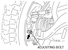
Maximum Steering Angle Adjustment
1. Remove the cap.
2. Loosen the adjusting bolt locknut.
3. Turn the adjusting bolt to provide the correct turning angle.
4. After adjustment, tighten the locknut to the specified torque.
absggw00000695
|
5. Install the cap.
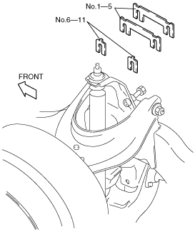
Caster and Camber Adjustment
1. Loosen the upper arm shaft bolt and insert or remove adjustment shims to provide the correct angle.
absggw00000696
|
Adjusting shim
|
No. |
Thickness (mm {in}) |
|---|---|
|
1
|
1.0 {0.039}
|
|
2
|
1.6 {0.063}
|
|
3
|
2.0 {0.079}
|
|
4
|
3.2 {0.126}
|
|
5
|
4.0 {0.157}
|
|
6
|
0.6 {0.024}
|
|
7
|
1.0 {0.039}
|
|
8
|
1.6 {0.063}
|
|
9
|
2.0 {0.079}
|
|
10
|
3.2 {0.126}
|
|
11
|
4.0 {0.157}
|
|
Shim thickness |
Variation/1 mm {0.039 in} |
|---|---|
|
Add
|
Negative 15′
|
|
Reduce
|
Positive 15′
|
|
|
Shim thickness |
Variation/1 mm {0.039 in} |
|---|---|---|
|
Front side
|
Add
|
Increase 30′
|
|
Reduce
|
Decrease 30′
|
|
|
Rear side
|
Add
|
Decrease 30′
|
|
Reduce
|
Increase 30′
|
2. After adjustment, tighten the upper arm shaft bolt to the specified torque.
3. Confirm the front wheel alignment as in the specification.
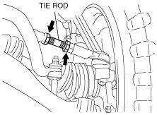
Total Toe-in Adjustment
1. Loosen the tie-rod end locknuts.
2. Turn the tie rods by the same amount in the opposite direction.
3. Tighten the tie-rod end locknuts.
absggw00000697
|