 |
absggw00001072
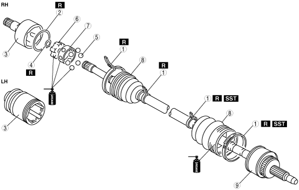
FRONT DRIVE SHAFT DISASSEMBLY/ASSEMBLY [WL-C, WE-C]
id0313008004g5
1. Disassemble in the order indicated in the table.
2. Assemble in the reverse order of disassembly.
absggw00001072
|
|
1
|
Boot band
(See Boot Band Assembly Note)
|
|
2
|
Clip
|
|
3
|
Outer ring
(See Outer Ring Assembly Note)
|
|
4
|
Snap ring
|
|
5
|
Balls
|
|
6
|
Inner ring
|
|
7
|
Cage
|
|
8
|
Boot
(See Boot Disassembly Note)
(See Boot Assembly Note)
|
|
9
|
Shaft and bell joint component
|
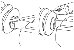
Boot Band Disassembly Note
1. Pry up the locking clips using a screwdriver.
absggw00001073
|
2. Remove the band using pliers.
3. Slide the boot along the shaft to expose the joint.
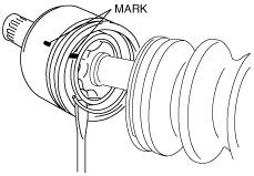
Outer Ring Disassembly Note
1. Mark the cage and outer ring for proper assembly.
2. Remove the clip using a screwdriver.
absggw00001074
|
3. Remove the outer ring from the inner ring and the balls.
4. Clean the grease away.
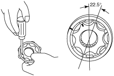
Balls, Inner Ring, Cage Disassembly Note
1. Mark the inner ring and cage.
2. Remove the snap ring using snap‐ring pliers.
3. Disassemble the balls, inner ring, cage from the drive shaft as component.
4. Turn the cage approx. 22.5 degree and pull the cage and balls away from the inner ring.
absggw00001075
|
Boot Disassembly Note
1. Wrap the shaft splines with tape.
absggw00001076
|
2. Remove the boot.
Boot Assembly Note
1. Fill the boot (wheel side) with the specified grease from a tube, not by hand.
2. With the splines of the shaft still wrapped in tape from disassembly, install the boot.
3. Remove the tape.
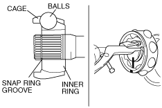
Cage, Inner Ring, Balls, Snap Ring Assembly Note
1. Align the marks and install the balls and cage to the inner ring in the direction shown in the figure.
absggw00001077
|
2. Install a new snap ring.
Outer Ring Assembly Note
1. Fill the outer ring and boot with the specified grease.
2. Align the marks, and install the outer ring on to the shaft.
3. Install a new clip.
4. Install the boot.
5. Set the drive shaft to the standard length.
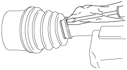
6. Release any trapped air from the boots by carefully lifting up the small end of each boot with a cloth wrapped screwdriver.
absggw00001078
|
7. Verify that the drive shaft length is within the specification.
Boot Band Assembly Note
Differential side
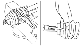
1. Fold the band in the direction opposite to the forward revolving direction of the drive shaft and use pliers to pull it tight.
absggw00001079
|
2. Lock the end of the band by bending the locking clips.
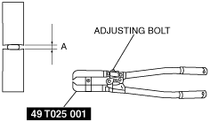
Wheel side (small boot band)
1. Adjust clearance A by turning the adjusting bolt of the SST.
absggw00001080
|
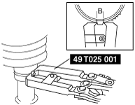
2. Crimp the wheel side small boot band using the SST. Verify that clearance B is within the specification.
absggw00001081
|
3. Verify that the boot band does not protrude from the boot band installation area.
4. Fill the boot with the repair kit grease.
Wheel side (big boot band)
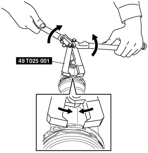
1. Tighten the wheel side big boot band by pinching the tabs shown in the figure.
absggw00001984
|
2. Set the end of the SST (49 T025 001) to the wheel side big boot band tabs at an angle, and tighten the wheel side big boot band.
absggw00001985
|
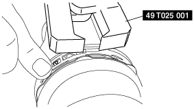
3. Tighten the wheel side big boot band until the projection is hooked.
absggw00001986
|
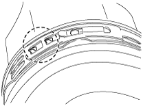
4. If the projection cannot be hooked, press the wheel side big boot band end with a finger to hook the projection.
absggw00001987
|
5. After tightening, verify that the wheel side big boot band projection is correctly hooked as shown in the figure.
absggw00001988
|
6. Verify that the boot band does not protrude from the boot band installation area.