 |
absggw00002410
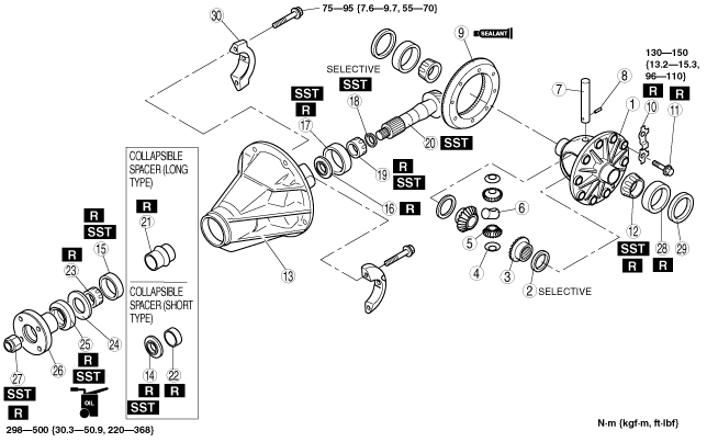
REAR DIFFERENTIAL ASSEMBLY [STANDARD DIFFERENTIAL]
id0314008006a1
1. Assemble in the order indicated in the table.
absggw00002410
|
|
1
|
Differential case
|
|
2
|
Thrust washer
(See Thrust Washer Assembly Note.)
|
|
3
|
Side gear
|
|
4
|
Thrust washer
|
|
5
|
Pinion gear
|
|
6
|
Thrust block
|
|
7
|
Pinion shaft
|
|
8
|
Knock pin
(See Knock Pin Assembly Note.)
|
|
9
|
Ring gear
(See Ring Gear Assembly Note.)
|
|
10
|
Lock plate (if equipped)
|
|
11
|
Bolt
|
|
12
|
Side bearing inner race
|
|
13
|
Differential carrier
|
|
14
|
Front oil baffle
|
|
15
|
Front bearing outer race
|
|
16
|
Rear oil baffle (if equipped)
|
|
17
|
Rear bearing outer race
|
|
18
|
Adjusting shim
(See Adjusting Shim Assembly Note.)
|
|
19
|
Rear bearing inner race
|
|
20
|
Drive pinion
(See Drive Pinion Assembly Note.)
|
|
21
|
Collapsible spacer (long type)
|
|
22
|
Collapsible spacer (short type)
|
|
23
|
Front bearing inner race
|
|
24
|
Thrust washer
|
|
25
|
Oil seal
(See Oil Seal Assembly Note.)
|
|
26
|
Companion flange
|
|
27
|
Locknut
(See Locknut Assembly Note.)
|
|
28
|
Side bearing outer race
|
|
29
|
Adjusting shim
|
|
30
|
Bearing cap
|
Thrust Washer Assembly Note
1. Adjust the backlash of the side gears and pinion gear as follows:
absggw00000862
|
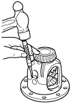
Knock Pin Assembly Note
1. Assemble the side gears, thrust washer, thrust block, pinion gears, pinion shaft and knock pin. After assembling the knock pin, make a crimp so that the pin will not come out of the gear case.
absggw00000863
|
Ring Gear Assembly Note
1. Coat the ring gear and gear case facing surfaces with locking agent.
2. Install the ring gear and tighten the bolt to the specified torque.
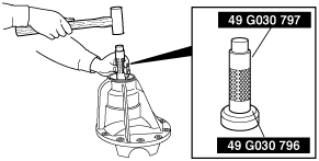
Side Bearing Inner Race Assembly Note
1. Press the side bearings into the gear case using the SST.
absggw00000864
|
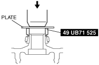
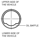
Front oil Baffle Assembly Note
1. Install the oil baffle in the direction shown in the figure.
abs0zw00000391
|
2. Tap the oil baffle into the differential carrier using the SSTs.
absggw00000865
|
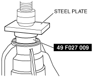
Front Bearing Outer Race Assembly Note
1. Press the front bearing outer race into the carrier using the SST and a press.
absggw00000866
|
Rear Oil Baffle Assembly Note
1. Install the oil baffle in the direction shown in the figure.
abs0zw00000391
|
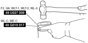
Rear Bearing Outer Race Assembly Note
F2, G6, WLT-1, WLT-2, WL-3
1. Press the rear bearing outer race into the differential carrier using the SSTs and a press.
absggw00000867
|
WL-C, WE-C
1. Press the rear bearing outer race into the differential carrier using the SSTs and a press.
absggw00002413
|
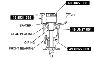
Adjusting Shim Assembly Note
Pinion height adjustment [F2, G6, WLT-1, WLT-2, WL-3]
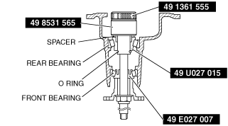
1. Assemble the spacer, rear bearing inner race and SST (49 UN27 004) on to the SST (49 8531 565). Secure the collar with the O-ring, then install this to the carrier.
absggw00000869
|
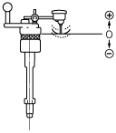
2. Assemble the front bearing inner race, SST (49 UN27 003), companion flange, washer and nut to the SST (49 8531 565).
3. Tighten the nut to the extent that the SST (49 8531 565) can be turned by hand.
4. Place the SST on the surface plate and set the dial indicator to zero.
absggw00000870
|
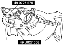
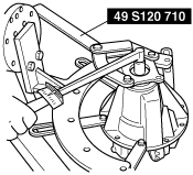
5. Place the SST (49 U027 008) on top of the SST (49 8531 565), and then set the SST (49 0727 570) on top of the SST (49 U027 008).
6. Place the measuring probe of the dial indicator so that it contacts the place where the side bearing is installed in the carrier, then measure left and right side of the lower position.
absggw00000871
|
7. Add the two (left and right) values obtained by the measurements taken in Step 6 and then divide the total by 2. From this sum, subtract the sum of the number inscribed on the end of the drive pinion divided by 100. (If there is no figure inscribed, use 0.) This is the pinion height adjustment value.
absggw00000872
|
Pinion height adjustment [WL-C, WE-C]
1. Assemble the spacer, rear bearing inner race and SST (49 U027 015) on to the SST (49 8531 565). Secure the collar with the O-ring, then install this to the carrier.
absggw00000873
|
2. Assemble the front bearing inner race, SST (49 E027 007), companion flange, washer and nut to the SST (49 8531 565).
3. Tighten the nut to the extent that the SST (49 8531 565) can be turned by hand.
4. Place the SST on the surface plate and set the dial indicator to zero.
absggw00000870
|
5. Place the SST (49 1361 555) on top of the SST (49 8531 565), and then set the SST (49 0727 570) on top of the SST (49 1361 555).
6. Place the measuring probe of the dial indicator so that it contacts the place where the side bearing is installed in the carrier, then measure left and right side of the lower position.
absggw00000874
|
7. Add the two (left and right) values obtained by the measurements taken in Step 6 and then divide the total by 2. From this sum, subtract the sum of the number inscribed on the end of the drive pinion divided by 100. (If there is no figure inscribed, use 0.) This is the pinion height adjustment value.
absggw00000872
|
Rear Bearing Inner Race Assembly Note
1. Press the rear bearing inner race using the SST.
absggw00000875
|
Drive Pinion Assembly Note
Drive pinion preload adjustment
1. Assemble the following parts to the drive pinion.
2. Adjust the preload of the drive pinion bearing as follows:
absggw00000876
|
Oil Seal Assembly Note
1. Apply differential oil to the lip of a new oil seal.
2. Press the oil seal in until it touches the end of the differential carrier using the SST.
absggw00000877
|
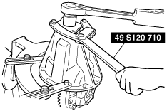
Locknut Assembly Note
1. Assemble the companion flange and washer.
2. Tighten the new locknut using the SST.
absggw00000878
|
3. Verify that the preload is within the specification.
Side Bearing Outer Race, Adjusting Shim, Bearing Cap Assembly Note
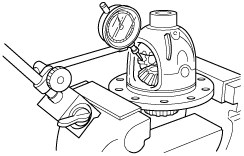
Ring gear backlash adjustment
1. Install the gear case component on the differential carrier.
2. Push the gear case component tot he left side of the differential carrier and measure the clearance between the side bearing and differential carrier. This measurement is the left and right total shim thickness.
3. Divide the amount of shim in step 2 appropriately between the right and left side, then install the bearing cap.
4. Adjust the drive pinion, ring gear backlash and the side bearing preload as follows:
absggw00000879
|
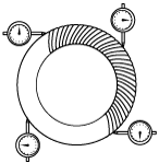
5. Inspect the backlash at the three other marked points and make sure that the minimum backlash is more than 0.05 mm {0.002 in} and difference of the maximum and minimum backlash value is less than 0.03 mm {0.001 in}.
absggw00000880
|
6. If backlash is not as specified, correct the backlash by switching whims from one side of the differential case to the other.
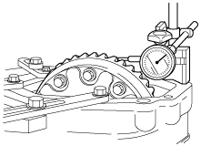
7. Using a torque wrench, inspect the total rotating torque of the pinion three complete revolutions, and then reading the rotating torque. The readings should not exceed 2.4 N·m {24.0 kgf·cm, 20.8 in·lbf}. If the backlash is within specification but the rotating torque is to high, the preload may be adjusted by removing an equal amount of shims from both sides of the differential.
8. The inspection and adjustment procedure is as follows:
absggw00001036
|
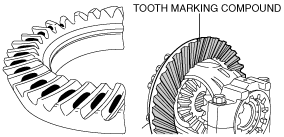
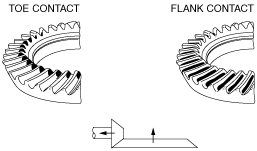
Toe and flank contact
1. Replace the spacer with a thinner one, and move the drive pinion outward.
absggw00001037
|
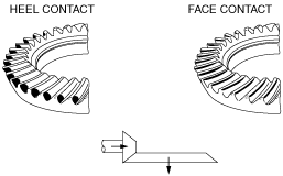
Heel and face contact
1. Replace the spacer with a thicker one. Bring the drive pinon inward.
absggw00001038
|