 |
absggw00001039
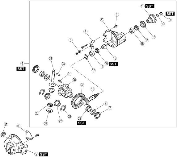
FRONT DIFFERENTIAL DISASSEMBLY
id031400801800
1. Disassemble in the order indicated in the table.
absggw00001039
|
|
1
|
Bolt
|
|
2
|
Differential casing
|
|
3
|
Oil baffle
|
|
4
|
Differential component
|
|
5
|
Lock plate
|
|
6
|
Bearing cap
(See Bearing Cap Disassembly Note.)
|
|
7
|
Adjusting screw
|
|
8
|
Side bearing outer race
|
|
9
|
Locknut
(See Locknut Disassembly Note.)
|
|
10
|
Washer
|
|
11
|
Companion flange
|
|
12
|
Oil seal
(See Oil Seal Disassembly Note.)
|
|
13
|
Drive pinion
|
|
14
|
Front bearing inner race
|
|
15
|
Collapsible spacer
|
|
16
|
Rear bearing inner race
|
|
17
|
Spacer
|
|
18
|
Front bearing outer race
|
|
19
|
Rear bearing outer race
|
|
20
|
Differential carrier
|
|
21
|
Bolt
|
|
22
|
Ring gear
|
|
23
|
Knock pin
(See Knock Pin Disassembly Note.)
|
|
24
|
Pinion shaft
|
|
25
|
Pinion gear
|
|
26
|
Thrust washer
|
|
27
|
Side gear
|
|
28
|
Thrust washer
|
|
29
|
Side bearing inner race
|
|
30
|
Gear case
|
|
31
|
Oil seal
|
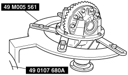
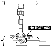
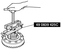
Differential Component Disassembly Note
1. Install the differential component to the SSTs.
absggw00001040
|
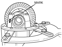
Bearing Cap Disassembly Note
1. Place a mark on one of the bearing caps so that the left and right bearing caps won’t get mixed up. Use the mark for matching at the time of assembly.
absggw00001041
|
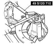
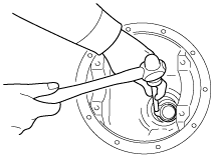
Locknut Disassembly Note
1. Hold the companion flange using the SST and remove the locknut.
absggw00001042
|
Companion Flange Disassembly Note
1. Pull the companion flange out using the SST.
absggw00001043
|
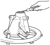
Oil Seal Disassembly Note
1. Remove the oil seal using a screw driver.
absggw00001044
|
Drive Pinion Disassembly Note
1. Remove the drive pinion by tapping with a plastic hammer.
absggw00001045
|
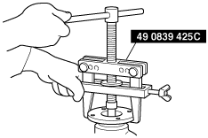
Rear Bearing Inner Race Disassembly Note
1. Remove the rear bearing inner race using the SST.
absggw00001046
|
Front Bearing Outer Race, Rear Bearing Outer Race Disassembly Note
1. Remove the bearing outer race by using the two grooves on the carrier and tapping the outer races alternately.
absggw00001047
|
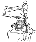
Knock Pin Disassembly Note
1. Secure the gear case in a vise and remove the knock pin using a 4 mm {0.16 in} diameter bar
absggw00001048
|
Side Bearing Inner Race Disassembly Note
1. Remove the side bearing inner race from the gear case using the SST.
absggw00001049
|