 |
arnffw00000206
FRONT DIFFERENTIAL ASSEMBLY [G6, WLT-1, WLT-2]
id0314008019c1
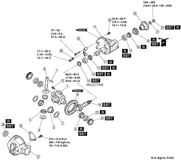
1. Assemble in the order indicated in the table.
arnffw00000206
|
|
1
|
Gear case
|
|
2
|
Thrust washer
|
|
3
|
Side gear
|
|
4
|
Thrust washer
|
|
5
|
Pinion gear
|
|
6
|
Pinion shaft
|
|
7
|
Knock pin
(See Knock Pin Assembly Note.)
|
|
8
|
Ring gear
(See Ring Gear Assembly Note.)
|
|
9
|
Side bearing inner race
|
|
10
|
Bolt
|
|
11
|
Differential carrier
|
|
12
|
Front bearing outer race
|
|
13
|
Rear bearing outer race
|
|
14
|
Spacer
(See Spacer Assembly Note)
|
|
15
|
Rear bearing inner race
|
|
16
|
Drive pinion
(See Drive Pinion Assembly Note.)
|
|
17
|
Collapsible spacer
|
|
18
|
Front bearing inner race
|
|
19
|
Oil seal (companion flange)
|
|
20
|
Companion flange
|
|
21
|
Washer
|
|
22
|
Locknut
(See Locknut Assembly Note.)
|
|
23
|
Side bearing outer race
|
|
24
|
Adjusting screw
|
|
25
|
Bearing cap
|
|
26
|
Lock plate
|
|
27
|
Differential casing
|
|
28
|
Oil seal (differential casing)
|
|
29
|
Oil baffle
|
|
30
|
Bolt
|
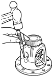
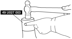
Knock Pin Assembly Note
1. Assemble the side gears, thrust washer, pinion gears, pinion shaft and knock pin. After assembling the knock pin, make a crimp so that the pin will not come out of the gear case.
arnffw00000207
|
Ring Gear Assembly Note
1. Coat the ring gear and gear case facing surfaces with locking agent.
2. Install the ring gear and tighten the bolt to the specified torque.
Side Bearing Inner Race Assembly Note
1. Press the side gearings into the gear case using the SST.
arnffw00000208
|
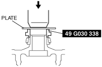
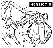
Front Bearing Outer Race Assembly Note
1. Press the front bearing outer race into the carrier using the SST and a press.
arnffw00000209
|
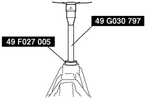
Rear Bearing Outer Race Assembly Note
1. Press the rear bearing outer race into the carrier using the SST and a press.
arnffw00000210
|
Spacer Assembly Note
Pinion height adjustment
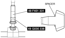
1. Assemble the spacer, rear bearing inner race, and the SST (49 8531 568) on to the SST (49 8531 565) as shown in the figure.
arnffw00000552
|
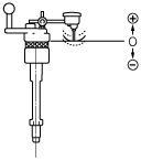
2. Assemble the front bearing inner race, SST (49 8531 567), companion flange, washer and nut to the SST (49 8531 565).
3. Tighten the nut to the extent that the SST (49 8531 565) can be turned by hand.
4. Place the SST on the surface plate and set the dial gauge to zero.
arnffw00000212
|
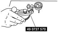
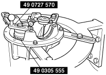
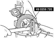
5. Place the SST (49 0305 555) on top of the SST (49 8531 565), and then set the SST (49 0727 570) on top of the SST (49 0305 555).
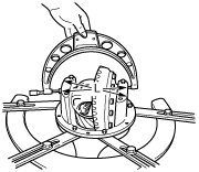
6. Place the measuring probe of the dial gauge at the point where the side bearing is installed in the differential carrier and measure at the lowest position. Measure the left and right sides.
arnffw00000553
|
7. Add the two (left and right) values obtained by the measurements taken in Step 6 and then divide the total by 2. From this sum, subtract the sum of the number inscribed on the end of the drive pinion divided by 100. (If there is no figure inscribed, use 0.) This is the pinion height adjustment value.
arnffw00000214
|
Spacer table
|
Identification mark |
Thickness (mm {in}) |
Identification mark |
Thickness (mm {in}) |
|---|---|---|---|
|
08
|
3.080 {0.1213}
|
29
|
3.290 {0.1295}
|
|
11
|
3.110 {0.1224}
|
32
|
3.320 {0.1307}
|
|
14
|
3.140 {0.1234}
|
35
|
3.350 {0.1319}
|
|
17
|
3.170 {0.1248}
|
38
|
3.380 {0.1331}
|
|
20
|
3.200 {0.1260}
|
41
|
3.410 {0.1343}
|
|
23
|
3.230 {0.1271}
|
44
|
3.440 {0.1354}
|
|
26
|
3.260 {0.1283}
|
47
|
3.470 {0.1366}
|
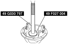
Rear Bearing Inner Race Assembly Note
1. Press the rear bearing inner race in using the SSTs.
arnffw00000215
|
Drive Pinion Assembly Note
Drive pinion preload adjustment
1. Assemble the following parts to the drive pinion.
2. Turn the serrated part of the drive pinion by hand to seat the bearing.
3. Tighten the locknut temporarily tightened in Step 1 from the lower limit of the specified tightening torque using the SST, and obtain the specified preload. Record the tightening torque at this time.
arnffw00000216
|
4. Remove the locknut, washer, and companion flange.
Oil Seal (Companion Flange) Assembly Note
1. Apply differential oil to the oil seal lip and press the oil seal in until it touches the end of the differential carrier using the SST.
arnffw00000225
|
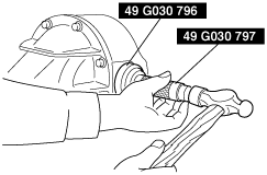
Locknut Assembly Note
1. Assemble the companion flange and washer.
2. Tighten a new locknut using the SST.
arnffw00000218
|
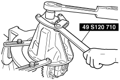
Side Bearing Outer Race, Adjusting Screw, Bearing Cap Assembly Note
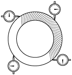
1. Install the differential gear component to the carrier. After loosely tightening the bearing outer race and bearing cap mounting bolts, completely tighten the adjustment screw by hand. Then, while turning the ring gear, alternately tighten the left and right adjustment screws using the SST.
arnffw00000219
|
2. Adjust the drive pinion, ring gear backlash and the side bearing preload as follows:
arnffw00000220
|
arnffw00000221
|
arnffw00000222
|
3. The inspection and adjustment procedure is as follows:
arnffw00000226
|
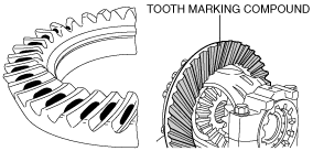
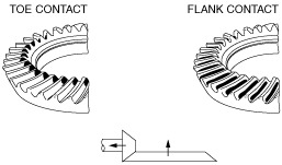
Toe and flank contact
1. Replace the spacer with a thinner one, and move the drive pinion outward.
arnffw00000227
|
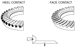
Heel and face contact
1. Replace the spacer with a thicker one. Bring the drive pinion inward.
arnffw00000228
|
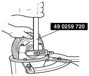
Oil Seal (Differential Casing) Assembly Note
1. Tap in the new oil seal to the front differential casing using the SSTs.
arnffw00000223
|