|
absggw00002344
PROPELLER SHAFT DISASSEMBLY/ASSEMBLY [REAR]
id0315008004e3
1. Disassemble in the order indicated in the table.
2. Assemble in the reverse order of disassembly.
absggw00002344
|
|
1
|
Snap ring
(See Snap Ring Disassembly Note.)
|
|
2
|
Bearing cup
(See Bearing Cup Disassembly Note.)
|
|
3
|
Spider
|
|
4
|
Yoke or flange yoke
|
|
5
|
Locknut
|
|
6
|
Washer
|
|
7
|
Yoke
|
|
8
|
Bearing support
|
|
9
|
Dust cover
(See Dust Cover Disassembly Note.)
(See Dust Cover Assembly Note.)
|
|
10
|
Propeller shaft No.1
|
|
11
|
Propeller shaft No.2
|
|
12
|
Boot band
|
|
13
|
Propeller shaft No.2
|
|
14
|
Boot
|
|
15
|
Propeller shaft No.3
|
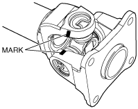
Snap Ring Disassembly Note
1. Place an alignment mark on the yoke and propeller shaft, or on the yoke and propeller shaft.
acmzzw00000008
|
2. Remove the snap ring.
Bearing Cup Disassembly Note
1. Remove the bearing cup from the propeller shaft using the SSTs and a press.
acmzzw00000009
|
2. Remove the bearing cup on the opposite side by following the same procedure.
3. Remove the propeller shaft from the yoke.
4. Remove the bearing cup from the yoke using the SSTs and a press.
5. Remove the bearing cup on the opposite side by following the same procedure.
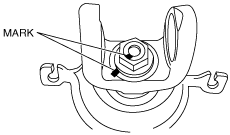
Locknut, Washer, Yoke Disassembly Note
1. Place alignment marks on the yoke and propeller shaft.
absggw00002326
|
2. Secure the yoke on the vise.
3. Remove the locknut and washer.
4. Remove the yoke.
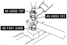
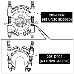
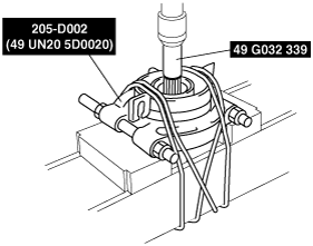
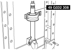
Bearing Support Disassembly Note
1. Install the SST as shown in the figure.
acmzzw00000011
|
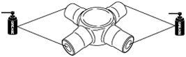
2. Tighten the SST nuts equally on the left and right.
acmzzw00000012
|
3. Set the rope as shown in the figure.
acmzzw00000013
|
4. Remove the bearing support using the SSTs and a press.
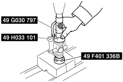
Dust Cover Disassembly Note
1. Remove the dust cover using the SST and a press.
acmzzw00000014
|
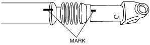
Boot Band, Propeller Shaft No.2, Boot, Propeller Shaft No.3 Disassembly Note
1. Remove the boot bands from the propeller shaft.
2. Place alignment marks as shown in the figure for proper installation.
acmzzw00000015
|
3. Remove the propeller shaft No.2.
4. Remove the boot.
5. Clean the propeller shaft splines.
6. Inspect the propeller shaft splines for damage, abnormal wear, dents, flaking, or bending.
Propeller Shaft No.3, Boot, Propeller Shaft No.2, Boot Band Assembly Note
1. Apply grease to the propeller shaft splines.
2. Assemble the boot.
3. Align the alignment marks on the propeller shaft, and assemble.
acmzzw00000015
|
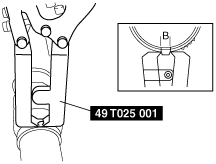
4. Adjust clearance A by turning the adjusting bolt of the SST.
acxaaw00000438
|
5. Crimp the boot band using the SST. Verify that clearance B is within the specification.
acmzzw00000016
|
6. Verify that the boot band does not protrude from the boot band installation area.
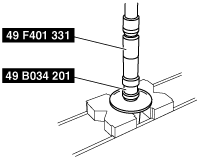
Dust Cover Assembly Note
1. Assemble the dust cover using the SSTs and a press.
acmzzw00000017
|
Bearing Support Assembly Note
1. Assemble the bearing support using the SST and a press.
acmzzw00000018
|
Yoke, Washer, Locknut Assembly Note
1. Secure the yoke on the vise.
2. Align the alignment marks on the propeller shaft and yoke, and assemble.
absggw00002326
|
3. Install the washer and locknut.
Bearing Cup, Snap Ring Assembly Note
1. Inject grease to the spider holes. (4x2)
acmzzw00000019
|
2. Set the new spider on the yoke and assemble a new bearing cup using the SSTs and a press until the snap ring groove can be seen.
acmzzw00000020
|
3. Assemble the opposite side by following the same procedure.
4. Insert the bearing cup and adjust it so that the snap ring groove has the largest width and both sides have the same groove width.
5. Assemble the new snap ring.
6. Lightly tap the yoke using a copper hammer and press the snap ring to the yoke.
7. Verify that the spider has no excessive play.
8. Align the propeller shaft and yoke with the alignment mark and install.
9. Assemble the bearing cup and snap ring by following Steps 2—8.
10. Inject grease into the grease nipple. (4x4)
11. Lightly tap the universal joint outer edge using a plastic hammer to adjust the component to the proper position.